HS50_advance_level 1_20200522_221201 (1).pdf - 第323页
1 - 2 Conte nts Studen t Guide HS-50 A d vance d I 06/200 2 Edition 2

Page
Contents 0
Student Guide HS-50 Advanced I Contents
06/2002 Edition
1
8 Gantry. . . . . . . . . . . . . . . . . . . . . . . . . . . . . . . . . . . . . . . . . . . . . . . . . . . . . . . . . . . . . 1
8.1 PCB Camera. . . . . . . . . . . . . . . . . . . . . . . . . . . . . . . . . . . . . . . . . . . . . . . . . . . . . . . . . . . . . . . . . . . . 1
8.1.1 Tools and equipment. . . . . . . . . . . . . . . . . . . . . . . . . . . . . . . . . . . . . . . . . . . . . . . . . . 1
8.1.2 Parts . . . . . . . . . . . . . . . . . . . . . . . . . . . . . . . . . . . . . . . . . . . . . . . . . . . . . . . . . . . . . . 1
8.1.3 Removal of the PCB Camera. . . . . . . . . . . . . . . . . . . . . . . . . . . . . . . . . . . . . . . . . . . 1
8.1.4 Fitting the PCB Camera Module . . . . . . . . . . . . . . . . . . . . . . . . . . . . . . . . . . . . . . . . . 2
8.1.5 Settings . . . . . . . . . . . . . . . . . . . . . . . . . . . . . . . . . . . . . . . . . . . . . . . . . . . . . . . . . . . . 2
8.2 Proximity Switch X- / Y- Axis . . . . . . . . . . . . . . . . . . . . . . . . . . . . . . . . . . . . . . . . . . . . . . . . . . . . . . 3
8.3 Settings and Illustrations . . . . . . . . . . . . . . . . . . . . . . . . . . . . . . . . . . . . . . . . . . . . . . . . . . . . . . . . . 4
8.3.1 Jumper Settings on Head Board S50 . . . . . . . . . . . . . . . . . . . . . . . . . . . . . . . . . . . . . 4
8.3.2 Jumper Settings, Processor Board S50 . . . . . . . . . . . . . . . . . . . . . . . . . . . . . . . . . . . 6
8.3.3 Jumper Settings, Gantry Distributor S50. . . . . . . . . . . . . . . . . . . . . . . . . . . . . . . . . . . 7
8.3.4 Proximity Switch Connectors on the X- / Y Distributor S50. . . . . . . . . . . . . . . . . . . . . 8
8.4 Calibration of the Anti - Crash Board. . . . . . . . . . . . . . . . . . . . . . . . . . . . . . . . . . . . . . . . . . . . . . . 10
8.4.1 Test Equipment . . . . . . . . . . . . . . . . . . . . . . . . . . . . . . . . . . . . . . . . . . . . . . . . . . . . . 10
8.4.2 Test Setup. . . . . . . . . . . . . . . . . . . . . . . . . . . . . . . . . . . . . . . . . . . . . . . . . . . . . . . . . 10
8.4.3 Adjustment of Distance Sensor Sensitivity . . . . . . . . . . . . . . . . . . . . . . . . . . . . . . . . 11
8.4.4 Calibration of the Anti - Crash Board. . . . . . . . . . . . . . . . . . . . . . . . . . . . . . . . . . . . . 11
8.4.5 Function Control of the Distance Sensor. . . . . . . . . . . . . . . . . . . . . . . . . . . . . . . . . . 11
8.4.5.1 Preparation. . . . . . . . . . . . . . . . . . . . . . . . . . . . . . . . . . . . . . . . . . . . . . . . . . . . . . . 11
8.4.5.2 Testing Placement Areas I and II . . . . . . . . . . . . . . . . . . . . . . . . . . . . . . . . . . . . . . 11
8.4.6 Functions Control of the Anti - Crash Board . . . . . . . . . . . . . . . . . . . . . . . . . . . . . . . 12
8.4.6.1 Preparation. . . . . . . . . . . . . . . . . . . . . . . . . . . . . . . . . . . . . . . . . . . . . . . . . . . . . . . 13
8.4.6.2 Test of the Proximity Switches on the Gantry. . . . . . . . . . . . . . . . . . . . . . . . . . . . . 13

1 - 2
Contents Student Guide HS-50 Advanced I
06/2002 Edition
2
Student Guide HS-50 Advanced I 06/2002 Edition
8 Gantry
1
8Gantry
8.1 PCB Camera
8.1.1 Tools and equipment
– Set of DIN 911 Allen keys
– SITEST program
8.1.2 Parts
PCB Optical Module KST Item-No: 00344065-02 8
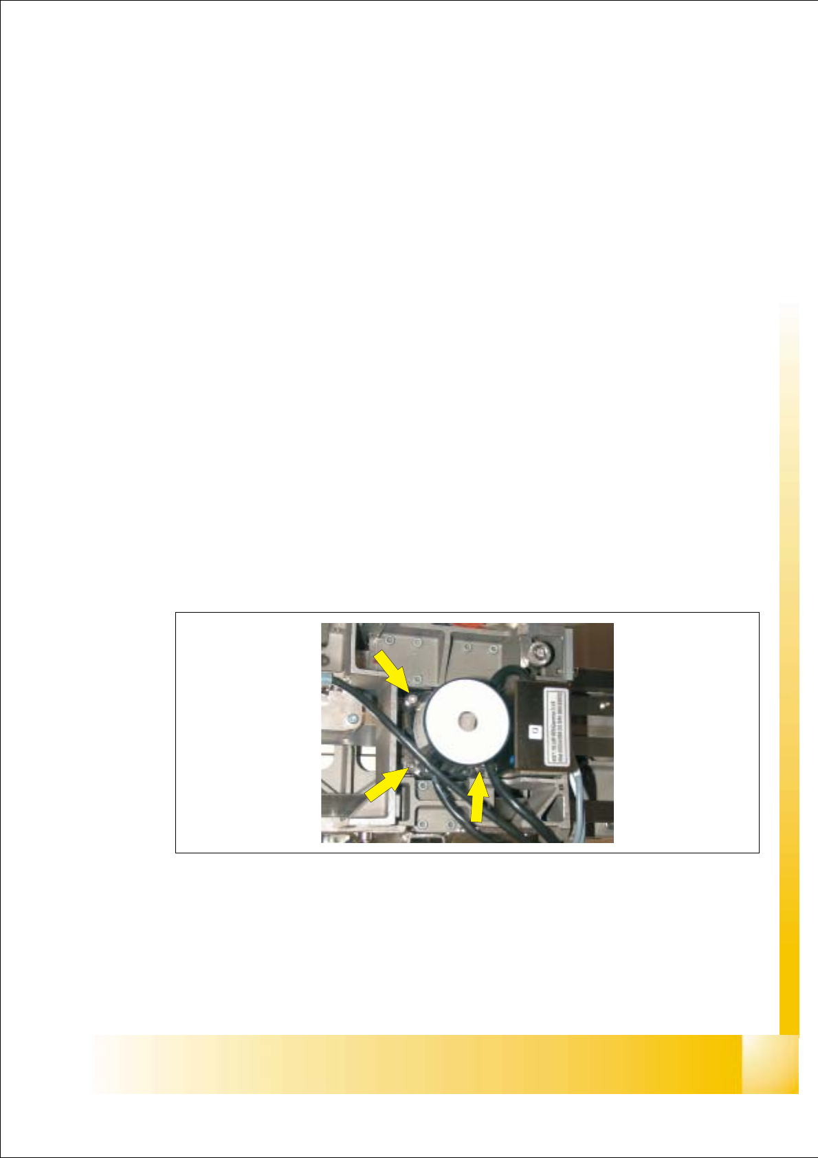
8.1.3 Removal of the PCB Camera
➠ Disconnect the Cable Camera Signal (see Fig: fig 8.3 - 1 Pos: 2) and cable illumination control
(see Fig: fig 8.3 - 1 Pos: 3) from the Head board HS-50.
➠ Remove the cable fixing straps.
➠ Loose the 3 Allen screws (see Fig: Fig. 8.1 - 1) and take the Camrea module out of the
machine.
Fig. 8.1 - 1 PCB Camera Module: Screws