00198150-02_SM_TX_en.pdf - 第101页
6 Gantries 6.3 Trailing Cable and Printed Circuit Boards Service Manual SIPLACE TX Series 06/2017 101 6.3.4.1 Gantry Interface 1/2 Fig.115: Gantry interface [03116147-xx] – Gantry 1 Fig.116: Gantry interface [03116149-…
6 Gantries
6.3 Trailing Cable and Printed Circuit Boards
100 Service Manual SIPLACE TX Series 06/2017
Removal
► Switch off the machine, disconnect it from the power supply and secure it to prevent
unauthorized reactivation. Observe the instructions in section 1.2 "Preparatory Work..." [}15].
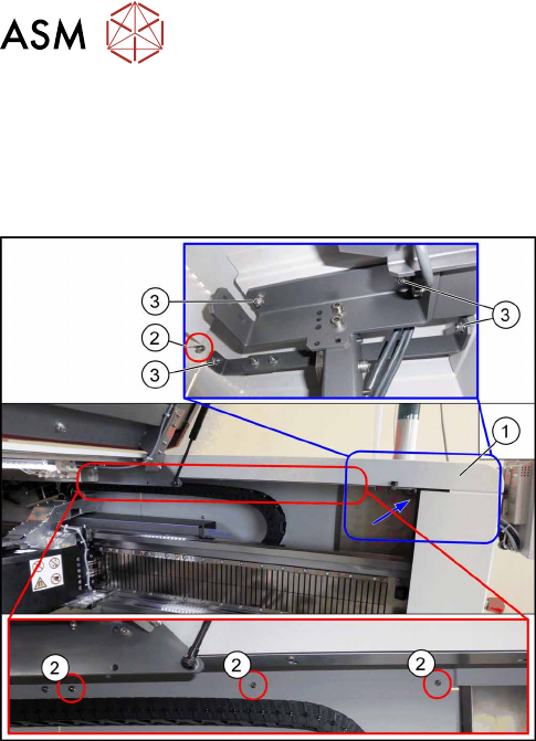
For a better access to the gantry interface you may remove the upper cover:
Fig.114: Removing the upper cover
► Remove the four nuts at(2) and the four nuts
at(3) on location1. Repeat for location2.
Ask for the help of a second person for the next step.
► Lift up the cover(1).
► Unplug all electrical connections to the gantry interface. You may want to mark the positions
of these connections to make clear assignment easier later on.
► Remove the six screws fastening the gantry interface and remove the gantry interface from
the machine.
Installation
► Follow the removal instructions in reverse order for installation.
6 Gantries
6.3 Trailing Cable and Printed Circuit Boards
Service Manual SIPLACE TX Series 06/2017 101
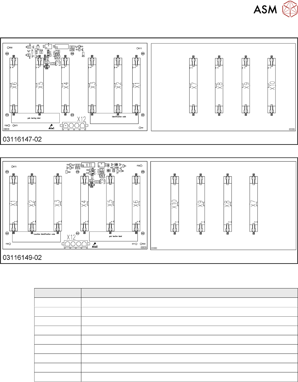
6.3.4.1 Gantry Interface 1/2
Fig.115: Gantry interface [03116147-xx] – Gantry 1
Fig.116: Gantry interface [03116149-xx] – Gantry 2
Connectors [03116147-xx] [03116149-xx]
Connector Description
X1/X2 Power Y motor flat ribbon cable
X3 Power X motor flat ribbon cable
X4/X8 150V / 40V
X5/X9 Power fail, FDB Bus MCAN,X temperature sensor
X6/X10 GigE
X7 Power X motor track signals X axis
X11 Track signals Y axis
X12 Power Y motor
X13 Temperature sensor
6 Gantries
6.3 Trailing Cable and Printed Circuit Boards
102 Service Manual SIPLACE TX Series 06/2017
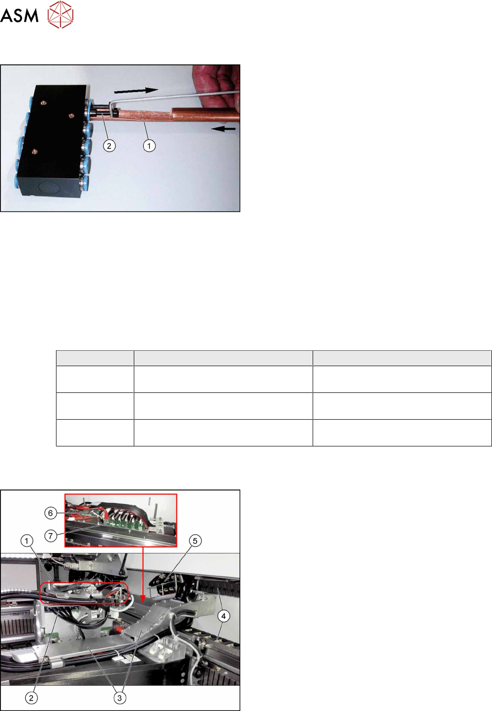
6.3.5 Handling the Hose Unlocking Tool [03047090-xx]
Fig.117: Unlocking Tool for Hoses and Blanking Plugs
Due to the poor access to the pneumatic distributor,
we recommend using the unlocking tool.
With the help of the hose unlocking tool [03047090-xx]
you can open the unlocking ring (blue here) for the
compressed air connection. This enables you to re-
move both the hoses and the blanking plugs (addi-
tional tool "Unlocking tool for QSC-10H" [03051853-
xx]).
Usage
► Use the pipe-shaped tool (1) to open the unlocking ring.
► Carefully pull the hose or the blanking plug(2) out of the compressed air connection.
6.3.6 Trailing cable
Parts, equipment and tools
Select the applicable trailing cable:
Trailing cable X axis Y axis
Gantry 1 Trailing cable X BG TX G1
[03112678‑xx]
Trailing cable Y TX G1 [03112680‑xx]
Gantry 2 Trailing cable X BG TX G2
[03112674‑xx]
Trailing cable Y TX G2 [03112675‑xx]
See 6.3.6.1 "Replacing the X Axis Trailing
Cable" [}103]
6.3.6.2 "Replacing the Y Axis Trailing
Cable" [}108]
Overview
Fig.118: Trailing cables
1. Boards on the gantry (shown without board cover
here)
2. Pneumatic distributor
3. Trailing cable console (covers)
4. Power track chain
5. Gantry Interface
6. Vision Base interface (VBI) [03115474‑xx]
7. GR X Y distribution SIPLACE TX [03110664‑xx]