00198150-02_SM_TX_en.pdf - 第126页
6 Gantries 6.4 MHCU, Boards and Camera 126 Service Manual SIPLACE TX Series 06/2017 ► Remove the two screws fastening the gantry sensor. ► Remove the gantry sensor carefully. Installation ► Follow the removal instruction…
6 Gantries
6.4 MHCU, Boards and Camera
Service Manual SIPLACE TX Series 06/2017 125
6.4.6 Replacing the Gantry Temperature Sensor
Parts, equipment and tools
●
MODUL / gantry sensor HCU [03112265‑xx]
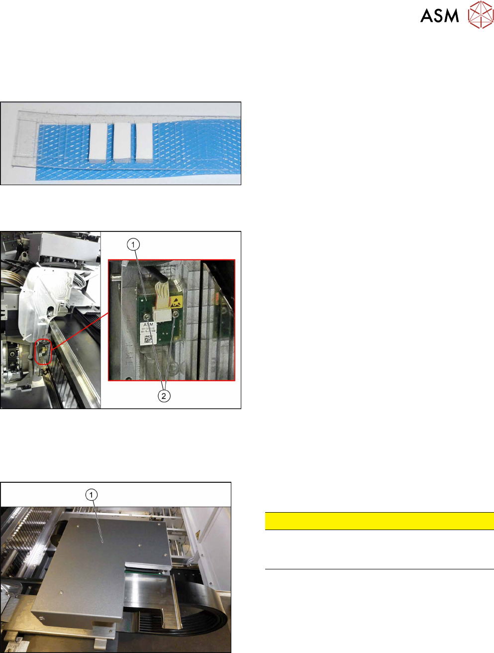
Fig.161: Gap filler
If required:
●
Silicon gap filler 7x7x16mm [03132222-xx]
Overview
Fig.162: Sensor on gantry
1. Gantry sensor HCU (temperature sensor)
2. Two fastening screws
Removal
► Switch off the machine, disconnect it from the power supply and secure it to prevent
unauthorized reactivation. Observe the instructions in section 1.2 "Preparatory Work..." [}15].
Fig.163: Board cover
► Remove the five fastening screws and lift the board
cover(1) off.
CAUTION!
Switch off the machine
To avoid short circuits, only dismantle the cover
when the machine is switched off!
.
► Remove the VHI (see 6.4.3 "Replacing the Vision Head Interface (VHI)
[03115454-xx]" [}117]).
► Unplug electric connection X4 on head interface (see also 6.4.4.1 "Head Interface
1/2" [}122]).
► Remove cable ties where necessary.
6 Gantries
6.4 MHCU, Boards and Camera
126 Service Manual SIPLACE TX Series 06/2017
► Remove the two screws fastening the gantry sensor.
► Remove the gantry sensor carefully.
Installation
► Follow the removal instructions in reverse order for installation. Also observe the following in-
structions:
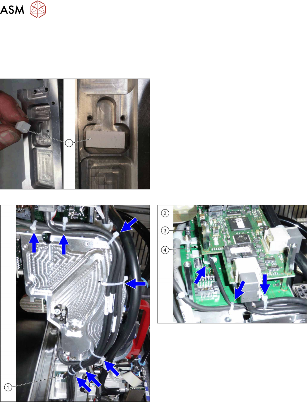
Fig.164: Gap filler
► If not present, use a gap filler.
Fig.165: Cable tie
1. Gantry temperature sensor
2. Vision Head interface
3. Head interface
4. Connection X4 on head interface
Blue arrows = cable ties
► Replace the cable ties which you removed be-
fore.
6 Gantries
6.4 MHCU, Boards and Camera
Service Manual SIPLACE TX Series 06/2017 127
6.4.7 Replacing the Sensor Module (SIPLACE TX micron only) [03134854‑xx]
Parts, equipment and tools
●
Sensor module [03134854‑xx]
Overview
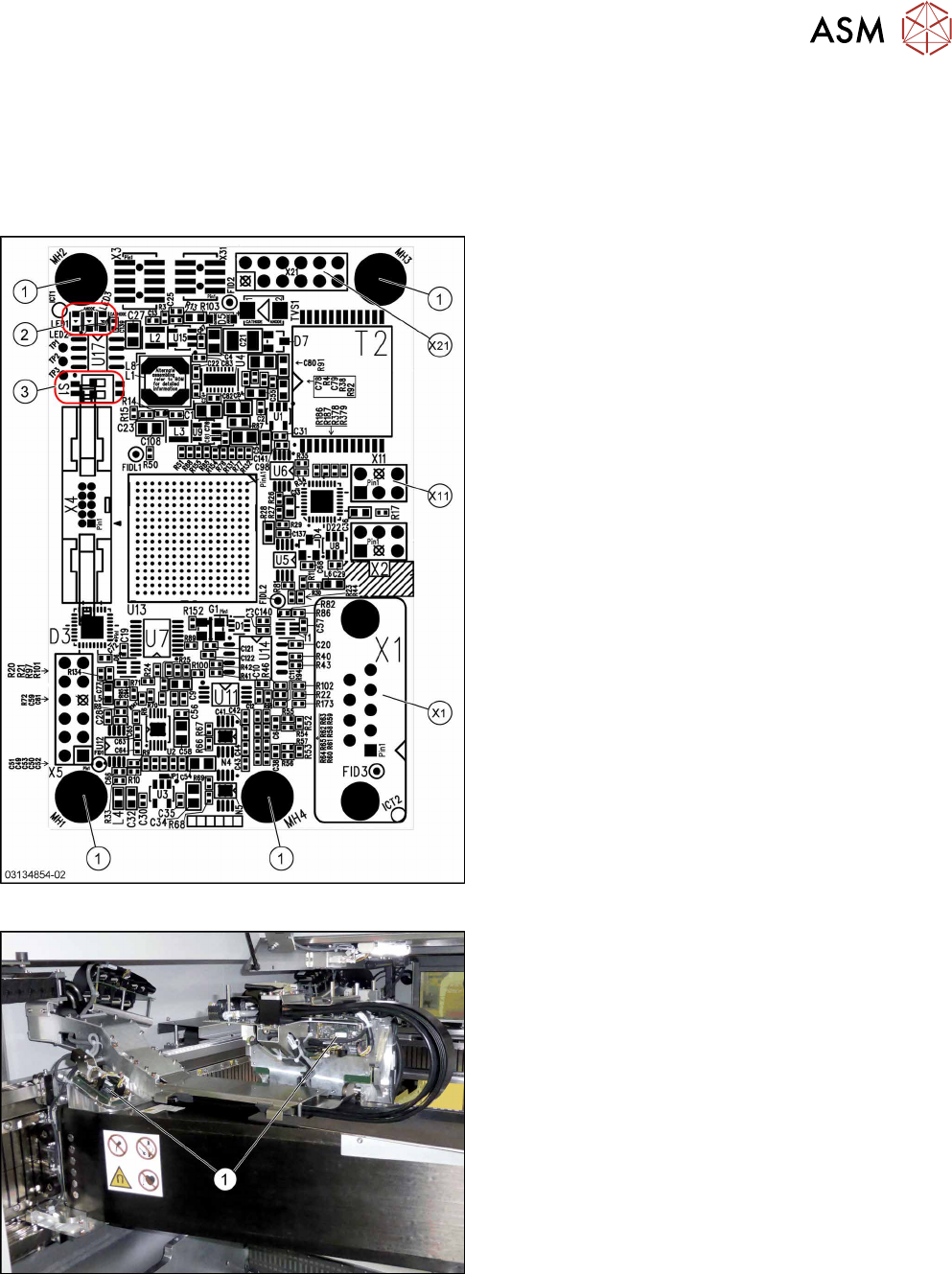
Fig.166: Sensor module universal
Sensor module universal [03134854‑xx]:
1. Fastening screws
2. LED 1/2/3
3. DIP switch S1
DIP Switch S1:
S1.1: OFF
S1.2: OFF
Connectors:
X1: Track signals analog
X2: not connected
X3: not connected
X4: not connected
X5: not connected
X11: Temperature sensor X/Y motor
X21: Track signals digital to gantry interface
X31: not connected
LEDs:
LED 1: flashing green → FPGA done
LED 2: yellow → FPGA initialized
LED 3: red → FPGA reset
Fig.167: Sensor module universal (without cover)
1. Sensor module universal
There are two universal sensor modules on each
SIPLACE TX micron machine, one for the X and one
for the Y axis.