00198150-02_SM_TX_en.pdf - 第213页
8 Placement Heads and Stationary Cameras 8.5 Installation Positions on the Head Plate Service Manual SIPLACE TX Series 06/2017 213 8.5 Installation Positions on the Head Plate NOTICE Example The installation positions ar…

8 Placement Heads and Stationary Cameras
8.4 Replacing the SIPLACE TwinHead
212 Service Manual SIPLACE TX Series 06/2017
Installation
► Follow the removal instructions in reverse order for installation. Also observe the following in-
structions:
CAUTION
Installation instructions
► Fit the fastening screws on the other side of the module, if needed (see above).
► Make a note of the force values for the new module. These force values can be found
on a label at the side of the module.
► Make sure that the assembly position is correct.
► Fasten the four screws with a torque of 2.7Nm.
► Perform a head calibration.
See also
2 Calibration [}222]
2 Calibrating the Heads and Cameras (SW70x) [}223]
8 Placement Heads and Stationary Cameras
8.5 Installation Positions on the Head Plate
Service Manual SIPLACE TX Series 06/2017 213
8.5 Installation Positions on the Head Plate
NOTICE
Example
The installation positions are showed using the example of gantry1.
► The installation positions are the same for gantry2.
See also
2 Replacing Attachment Head Suspension [03124850-xx] [}93]
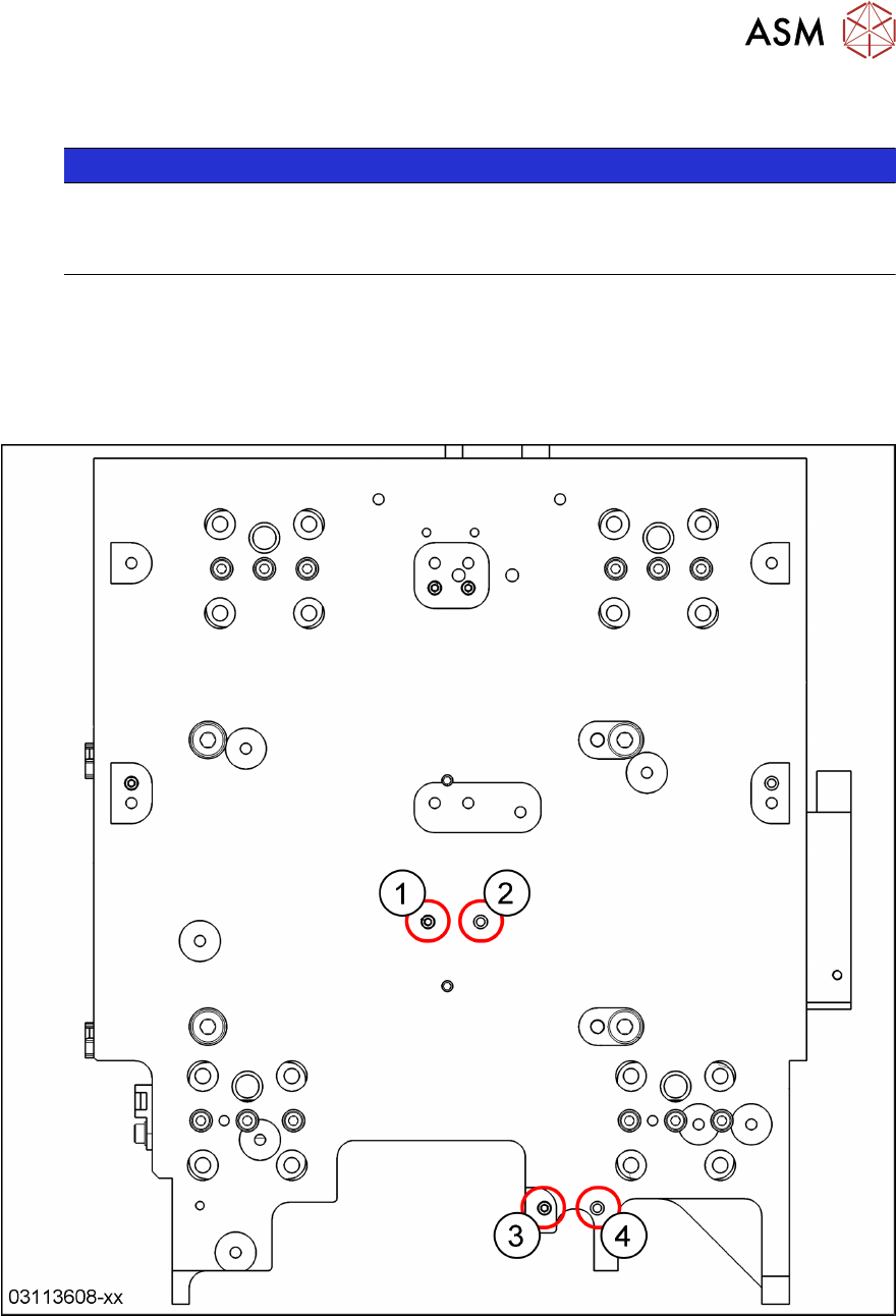
8.5.1 Gantry 1 – Positions of Treaded Pins when Changing from C&P20 P to CPP
and Reverse
Fig.292: Gantry 1: C&P20P head → CPP head
1 C&P20P: threaded pin
CPP: empty
2 C&P20P: empty
CPP: threaded pin
3 C&P20P: threaded pin
CPP: empty
4 C&P20P: empty
CPP: threaded pin
8 Placement Heads and Stationary Cameras
8.5 Installation Positions on the Head Plate
214 Service Manual SIPLACE TX Series 06/2017
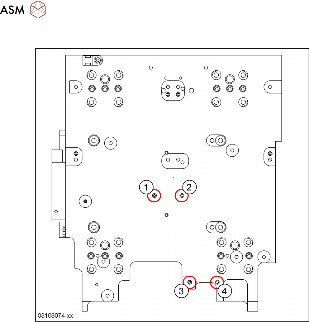
8.5.2 Gantry 2 – Positions of Treaded Pins when Changing from C&P20 P to CPP
and Reverse
Fig.293: Gantry 2: C&P20P head → CPP head
1 C&P20P: threaded pin
CPP: empty
2 C&P20P: empty
CPP: threaded pin
3 C&P20P: threaded pin
CPP: empty
4 C&P20P: empty
CPP: threaded pin