00198150-02_SM_TX_en.pdf - 第266页
11 Cutter 11.9 Replacing the Cutter Blades 266 Service Manual SIPLACE TX Series 06/2017 Fig.370: Movable blade ► Loosen the movable blade (2) from the piston (1) of the short-stroke cylinder. CAUTION! Risk of injury…
11 Cutter
11.9 Replacing the Cutter Blades
Service Manual SIPLACE TX Series 06/2017 265
Removal
► Switch off the machine, disconnect it from the power supply and secure it to prevent
unauthorized reactivation. Observe the instructions in section 1.2 "Preparatory Work..." [}15].
► Remove the cutter from the machine.
Replacing the Cutter on the COT Insert [03066690-xx] [}252]
Fig.367: Cover plate
► Remove the screws(2) fastening the top cover
plate(1) and then remove the top cover plate.
Fig.368: Baffle plate
► Remove the two screws(1) at the front side and
five screws(2) at the inner side fastening the
baffle plate.
► Remove the baffle plate unit from the cutter.
Fig.369: Plastic caps
From the bottom side of the cutter you have easy ac-
cess to the plastic cap.
► Remove the plastic caps(1) over the fastening
screws on both sides of the movable blade.
► Remove the two screws.
11 Cutter
11.9 Replacing the Cutter Blades
266 Service Manual SIPLACE TX Series 06/2017
Fig.370: Movable blade
► Loosen the movable blade(2) from the piston(1)
of the short-stroke cylinder.
CAUTION!
Risk of injury!
There is a risk of injuring yourself on the cutting
edge of the blades.
.
4
3
5
1
4
3
2
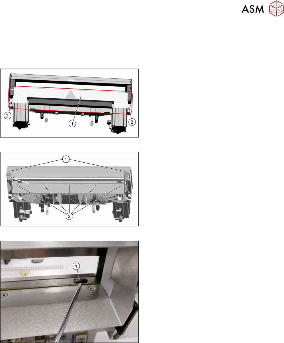
Fig.371: Cutter
► Remove the two screws(1) fastening the station-
ary blade(2).
► Remove the screws fastening the left and right
tape deflectors (3) above the moveable blade.
CAUTION!
Not all screws!
Do not loosen these two screws(4)!
.
► Remove the tape deflector holder with the tape
deflector(5) and carefully place the whole unit
down (with the tape deflector facing upwards).
3
4
1
5
4
3
2
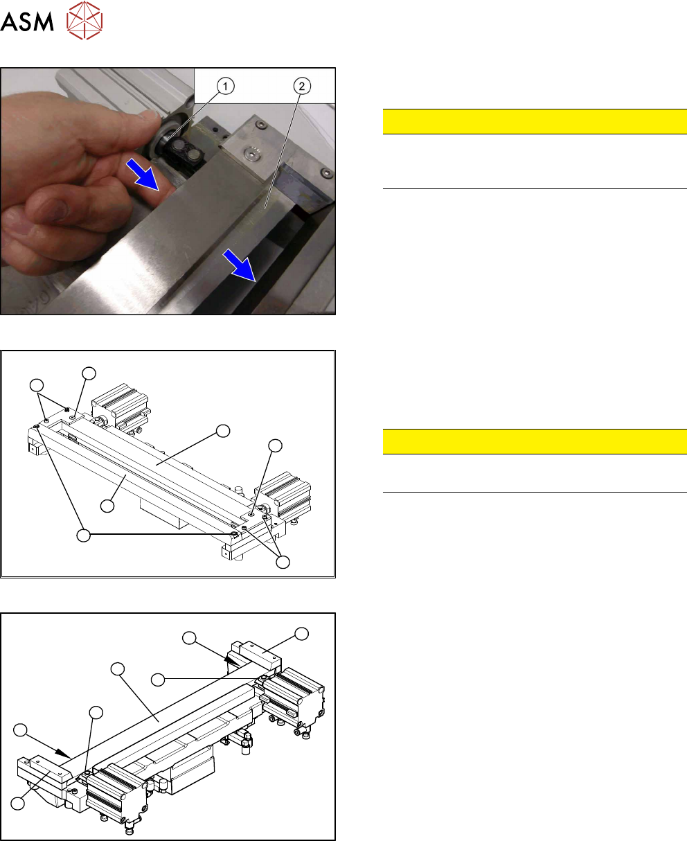
Fig.372: Cutter
► Remove the right-hand holding-down device (1)
and the left holding-down device (2), plus the
spacers below.
► Use an SW10 open-ended wrench to push
against the joint (3), while loosening the hexagon
socket-head screw of the joint (4) in the move-
able blade. This may require more strength than
usual as the screws have been secured with Loc-
tite243.
► Grasp both ends of the moveable blade (5) with
the protective gloves and pull it upwards and out.
11 Cutter
11.9 Replacing the Cutter Blades
Service Manual SIPLACE TX Series 06/2017 267
Installation – requirements
CAUTION
Risk of injury!
There is a high risk of injury from the blades and the tape deflector.
●
Wear appropriately thick protective gloves!
●
Make sure all parts are clean before installing them.
●
Do not use fat dissolving agents on the blades (risk of rust film forming).
●
The new blades are covered with a fine lubrication film.
The blades may only be greased with the lubricants described in the maintenance manual.
Any other lubricant would impair the movement of the moveable blade.
●
If the new blades are not clean, carefully clean them (wear protective gloves) with a clean
brush or a well folded, clean and dry cloth.
Installation – preparations
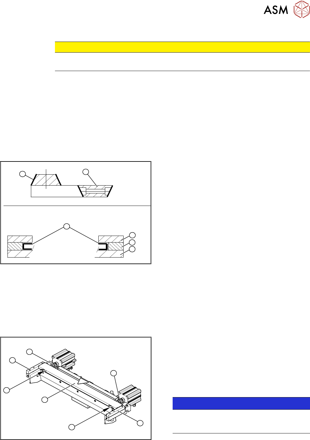
1
6
5
4
3
2
Fig.373: Blades
1. Stationary blade
2. Moveable blade
3. Sliding surfaces to be lubricated
4. Holding-down device
5. Spacer
6. Contact surface
► Make sure the cutter is in the correct rotary position (see the slant of the blade).
► Check the positioning of the individual blades to one another.
► Before installation, lubricate the sliding side surfaces of the moveable blade with Klüber BEM
34-132 and make sure that the recesses are filled. These will be refilled later on during main-
tenance with the lubrication nipples.
Installation
2
3
4
1
4
3
2
Fig.374: Cutter
► Correctly insert the moveable blade (1) into the
cutter and shift it along to its original installation
position.
► Apply Loctite243 to the two M4 screws to fasten
the joint in the moveable blade.
► Insert the screws (2) into the left and right holes,
provided in the moveable blade.
NOTICE!
Make sure that the joint (3) can slide into the slot
(=anti-twist function) in the moveable blade
without obstruction.
.
► Use an SW10 open-ended wrench to push against the relevant joint (3) and then tighten both
screws(2) to a torque of 6Nm.