00198150-02_SM_TX_en.pdf - 第303页
14 JEDEC Tray Feeder 14.1 SIPLACE JTF-ML Service Manual SIPLACE TX Series 06/2017 303 Fig.436: Connecting X1 ► Connect X1. Fig.437: Connecting the X4 ► Connect X4. Fig.438: Connecting the X3 ► Connect X3: Mount the fl…
14 JEDEC Tray Feeder
14.1 SIPLACE JTF-ML
302 Service Manual SIPLACE TX Series 06/2017
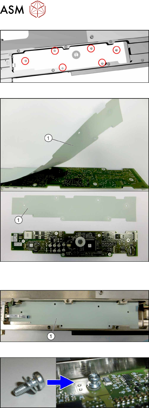
Fig.432: Removing the control board X adapter
► Remove the six screws (torxT10) fastening the
control board X adapter.
► Remove the control board X adapter.
Fig.433: Insulation layer
► Take care of the insulation layer(1) on the back-
side of the control board X adapter.
The isolation layer will be reused with the new
control board X adapter.
► Carefully remove the insulation layer from the
control board X adapter.
Installation
Fig.434: Positioning the insulation layer
► Place the old insulation layer in position.
Center the holes in the insulation layer to the
screw holes.
► Place the new control board X adapter in posi-
tion.
Center the holes in the control board to the screw
holes.
Fig.435: Fitting the control board X adapter
► Fix the control board X adapter with six fastening
screws (torx T10) hand-tight.
Take care to use all washers and circlips cor-
rectly.
14 JEDEC Tray Feeder
14.1 SIPLACE JTF-ML
Service Manual SIPLACE TX Series 06/2017 303
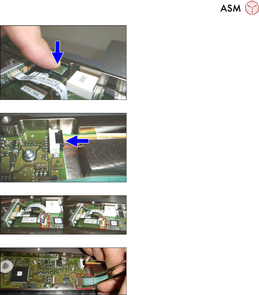
Fig.436: Connecting X1
► Connect X1.
Fig.437: Connecting the X4
► Connect X4.
Fig.438: Connecting the X3
► Connect X3:
Mount the flat ribbon cable into the X3 base.
Check that the connector is fully slipped in the X3
base and the cable runs parallel to the X3 base.
Close the interlock by folding it back.
► Check the correct connector locking by pulling
the flat ribbon cable gently.
Fig.439: Connecting the X17
► Connect X17:
Connect the flat ribbon cable to the X17 base.
Make sure that the cable is fully inserted into the
X17 base and that it runs parallel to the X17
base.
Close the interlock by pushing it back.
Use tweezers to push it.
► Check the correct connector locking by pulling
the flat ribbon cable gently.
14 JEDEC Tray Feeder
14.1 SIPLACE JTF-ML
304 Service Manual SIPLACE TX Series 06/2017
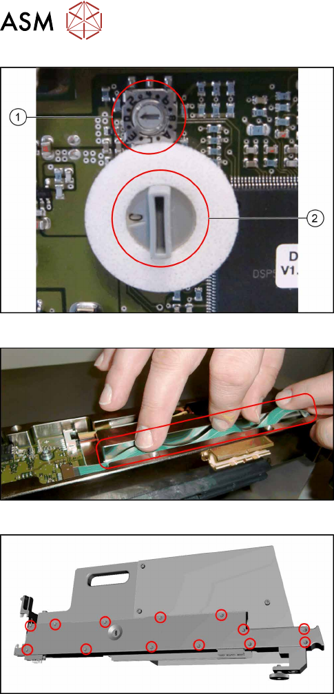
Fig.440: Checking the switches
► Check the switches for addressing and commu-
nication protocol:
1. The small switch must be set to "0".
2. The large switch must be set to "C".
Fig.441: Flat ribbon cable
► Take care not to fold the flat ribbon cable when
mounting the cover in the next step.
Fig.442: Fitting the cover
► Refit the cover.