00198150-02_SM_TX_en.pdf - 第140页
7 Conveyor 7.2 Lifting Table 140 Service Manual SIPLACE TX Series 06/2017 7.2.3 Replacing the Lifting Table Motor [03088241-xx] Parts, equipment and tools ● BLDC motor BG65x50 assembly with cables and connectors [0308824…
7 Conveyor
7.2 Lifting Table
Service Manual SIPLACE TX Series 06/2017 139
Removal
► Use the software or manually move the conveyor rail into a position which allows you best ac-
cess.
– To move the conveyor rail manually, pull the toothed belt of the width adjustment unit.
► Switch off the machine, disconnect it from the power supply and secure it to prevent
unauthorized reactivation. Observe the instructions in section 1.2 "Preparatory Work..." [}15].
► Move all gantries out of the transport area as far as possible at one side of the machine.
► Dismantle the lifting table plate (see 7.2.1 "Replacing the Lifting Table Plate
[03114873-xx]" [}136]).
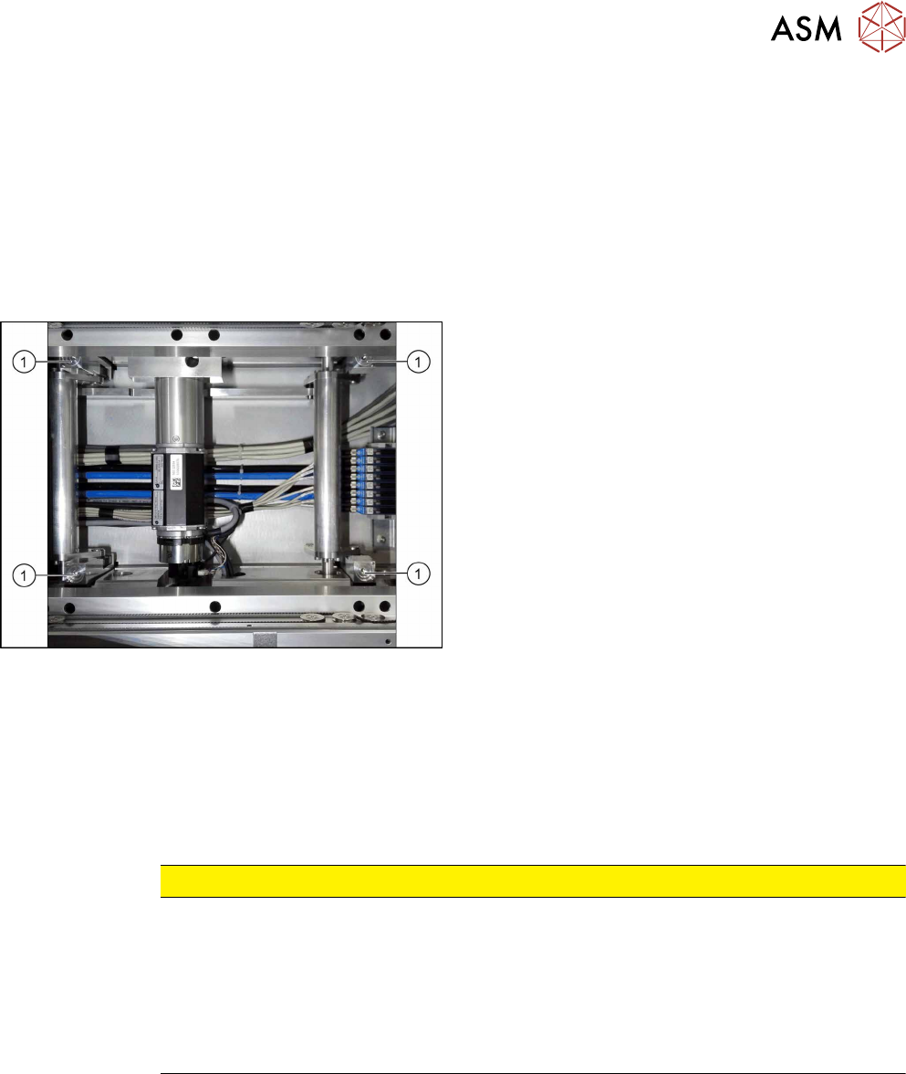
Fig.185: Lifting table plate guides
► Remove the relevant plate guide(1).
Installation
► Press in the two pins at the plate guide. Consider the right position depending on the position
in the lifting table. The pins are always on the outside position of the table.
► Insert the self-cutting screw in the center. You can precut the hole with this screw.
► Follow the removal instructions in reverse order for further installation. Also observe the fol-
lowing instructions:
CAUTION
Installation instructions
► Place the lifting table plate onto the guidance pins. Make sure that the fastening
screws slide properly into the precut thread.
► Check the parallelism of the lifting table plate (see 7.2.4 "Setting the Parallelism and
Height of the Lifting Table Plate" [}143]).
► Check the free movement of the lifting table (see 7.2.5 "Checking Free Movement of
Lifting Table" [}144]).
See also
2 Setting the Parallelism and Height of the Lifting Table Plate [}143]
7 Conveyor
7.2 Lifting Table
140 Service Manual SIPLACE TX Series 06/2017
7.2.3 Replacing the Lifting Table Motor [03088241-xx]
Parts, equipment and tools
●
BLDC motor BG65x50 assembly with cables and connectors [03088241-xx]
Overview
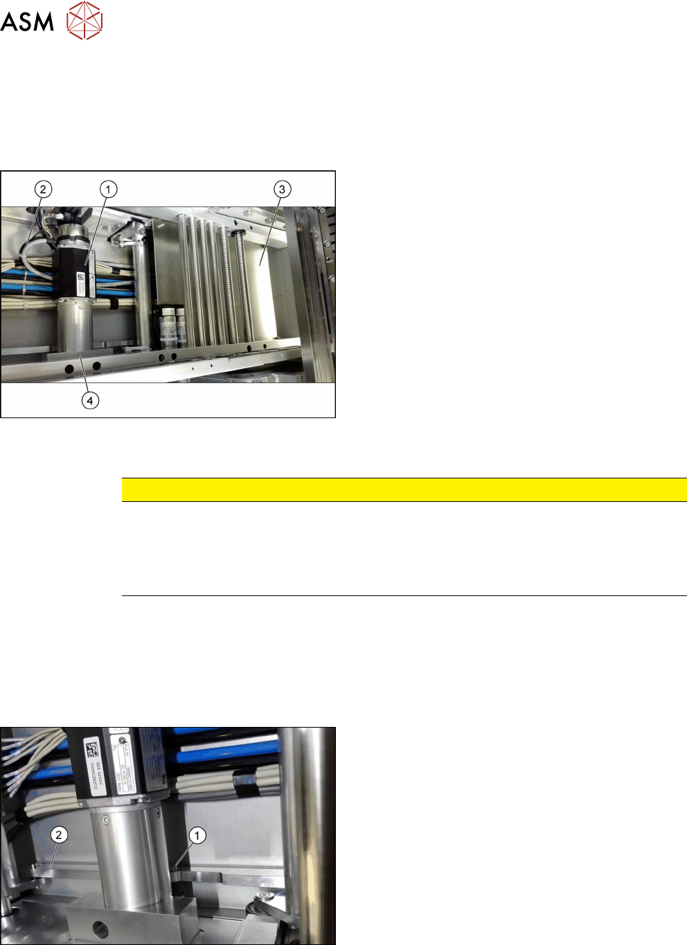
Fig.186: Lifting table motor - overview
1. Lifting table motor
2. Lifting table motor cable (connect to conveyor
control board)
3. Conveyor control board
4. Retaining bracket for the lifting table motor
Removal
CAUTION
Washers
There are washers at various points, for example between the lifting table motor and the
rods.
► Make a note of the number of washers and their positions. These will need to be fitted
again in the same places later on.
► Use the software or manually move the conveyor rail into a position which allows you best ac-
cess.
– To move the conveyor rail manually, pull the toothed belt of the width adjustment unit.
► Switch off the machine, disconnect it from the power supply and secure it to prevent
unauthorized reactivation. Observe the instructions in section 1.2 "Preparatory Work..." [}15].
► Move all gantries out of the transport area as far as possible at one side of the machine.
Fig.187: Lifting table motor
► Dismantle the lifting table plate (see 7.2.1 "Repla-
cing the Lifting Table Plate [03114873-
xx]" [}136]).
► Remove the screw(1) fastening the rods(2).
Carefully dismount the rods.
► Slightly pull the COT insert out of the machine.
Replacing the COTi Central Unit and Lifting Mechanics [}235]
7 Conveyor
7.2 Lifting Table
Service Manual SIPLACE TX Series 06/2017 141
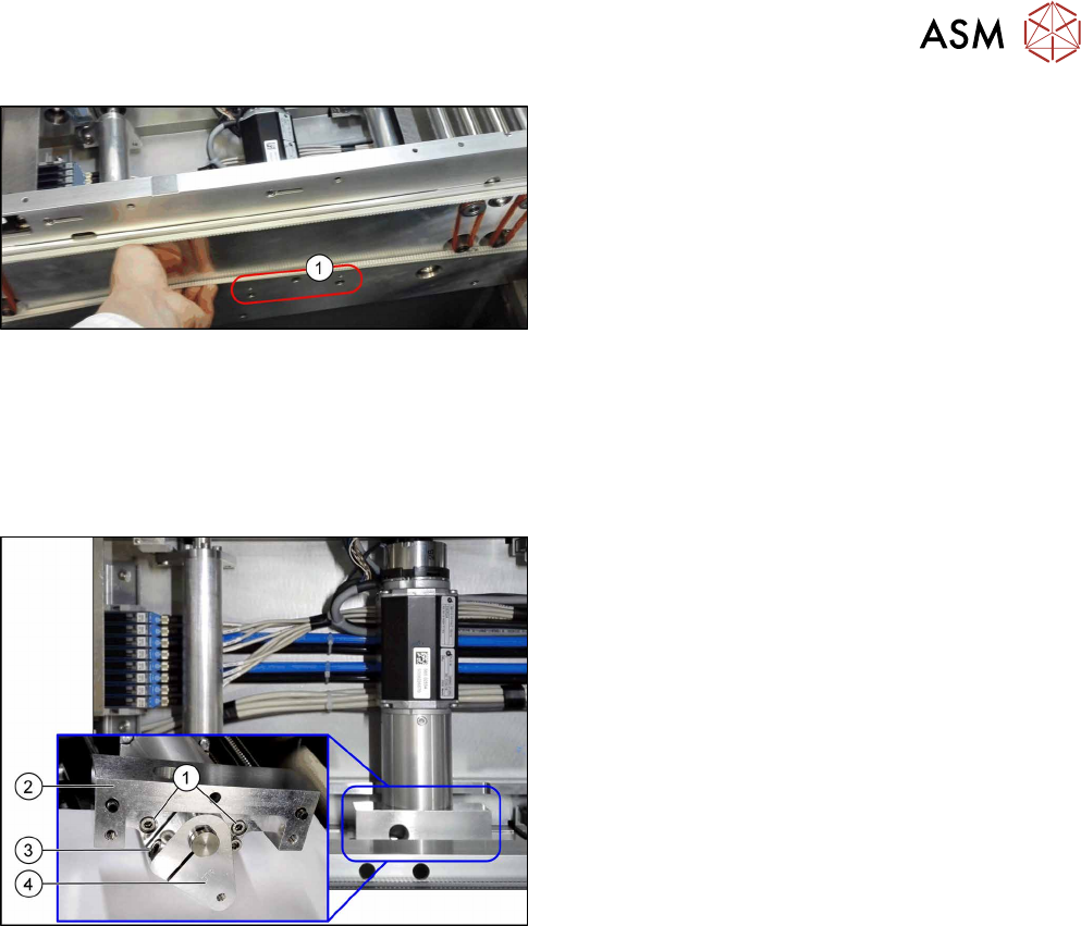
Fig.188: Fastening screws
► Remove the three screws(1) fastening the retain-
ing bracket.
► Dismantle the cover over the conveyor control board.
► Unthread the cable up to the conveyor control and then unplug it at connection X10. You may
want to mark the position to make clear assignment easier later on.
See also: 7.7.1.1 "Conveyor Control TSP420 [03087642-xx]" [}182]
► Remove the lifting table motor from the machine.
Fig.189: Motor crank and brackets
The motor crank(4) and the brackets(2) need to be
removed and refitted on the new lifting table motor.
► Remove the two screws(1) fastening the brack-
ets(2).
► Remove the screw(3) fastening the motor
crank(4).
Installation
► Follow the removal instructions in reverse order for installation. Also observe the following in-
structions: