00198150-02_SM_TX_en.pdf - 第14页
1 Introduction 1.1 Safety Instructions 14 Service Manual SIPLACE TX Series 06/2017 1.1.9 Safety Instructions for the Sensor of the Coplanarity Module The sensor works with a semiconductor laser of wave length 670 nm (vis…
1 Introduction
1.1 Safety Instructions
Service Manual SIPLACE TX Series 06/2017 13
1.1.6 Safety Instructions for the Gantry
CAUTION
Moving the gantry can damage the placement head.
When moving the gantry, observe the following:
► NEVER move the gantry by pushing with your hands against the placement head.
► NEVER push the gantry while the Z axis is lowered.
1.1.7 Safety Instructions on Hazardous Materials
CAUTION
Observe the safety data sheets
Observe the applicable safety data sheet, when handling hazardous materials (e. g. Loctite
241, ethanol).
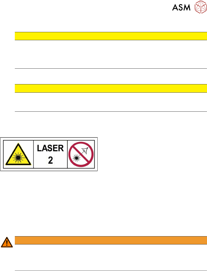
1.1.8 Classification of the Optical Systems
1.1.8.1 Classification of the Whole Machine
Fig.2: Laser class 2
The ready-to-operate overall machine is assigned
to laser class°2.
The laser classes are determined according to
DIN EN 60825-1:2014.
1.1.8.2 Laser Classification
The following modules are assigned to laser class 2:
●
Component sensor on the SpeedStar
●
Component sensor on the MultiStar
●
Laser light barriers at the board conveyor
1.1.8.3 Classification of the Camera Systems
WARNING
LEDs
The camera illumination systems are fitted with light LEDs. These are assigned to risk
group 1 according to IEC 62741:2006.
► Do not look into beam!
1 Introduction
1.1 Safety Instructions
14 Service Manual SIPLACE TX Series 06/2017
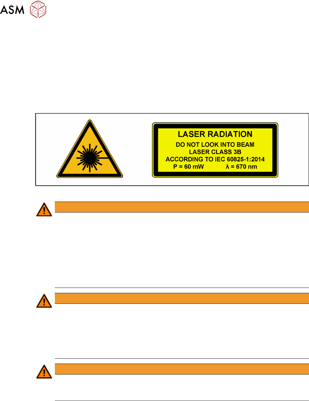
1.1.9 Safety Instructions for the Sensor of the Coplanarity Module
The sensor works with a semiconductor laser of wave length 670 nm (visible/red).
The maximum optical output performance is 60 mW.
The sensor is classified as laser class 3B.
► When operating the sensor, always follow the relevant regulations on "Radiation safety for
laser equipment" according to IEC60825‑1:2014 and the "Laser Radiation" (DGUV Direction
11) accident prevention regulation applicable in Germany.
► Also follow the accident prevention regulations applicable in your country.
The following information plates are attached to the front and back of the sensor housing:
Fig.3: Identification of laser class 3B for the sensor
WARNING
The laser radiation is a danger to the eye.
The accessible laser radiation is a danger to the eye and, in special cases, also to the skin.
Exposure to direct radiation or reflected radiation of class 3B lasers (medium performance)
is a danger to the eye. In the upper performance area, lasers can cause damage to the
skin.
► Never look directly into the laser beam.
► The 3D coplanarity module is secured and built into the machine in such a way that,
when used as prescribed (shortterm radiation), the accessible radiation complies with
laser class 2 and as a result is no danger to the eye.
WARNING
Encapsulated class 2 laser device
When fitted, the placement machine is classified as a so-called "encapsulated" class 2
laser device.
► The 3D sensor is integrated into the emergency STOP circuit.
► Do not disable the emergency STOP circuit!
► The 3D sensor may only be operated inside the placement machine!
WARNING
Repair and Service
► For repair and service, always return the sensors to ASM Assembly Systems GmbH &
Co. KG.
1 Introduction
1.2 Preparatory Work...
Service Manual SIPLACE TX Series 06/2017 15
1.2 Preparatory Work...
Purpose and scope
Before performing any preventive maintenance work, conversion work or service work, a procedure
of locking and tagging must be followed and warning signs must be attached if not stated other-
wise. If it is not necessary to switch off the machine, it is explicitly mentioned.
The procedure, when followed correctly, eliminates the possibility of an employee being injured.
NOTICE
Additional safety measures
This procedure represents the minimum lock out and tag out requirements for the machine
during preventive maintenance work and service work. Any additional safeguards needed
to complete work safely can be specified by facilities supervision, the safety officer, the
safety committee and the health department.
Description
Whenever it becomes necessary to isolate, control and release energy, the following procedure is
to be followed.
► Notify all affected employees.
► Switch off the machine and all additional devices. Carry out all normal stopping procedures:
ð Press the STOP button.
ð Shut down the station computer.
ð Switch off the machine using the main switch.
► Isolate the machine from all its energy sources:
ð Shut off the compressed air supply.
ð Shut off the main power supply.
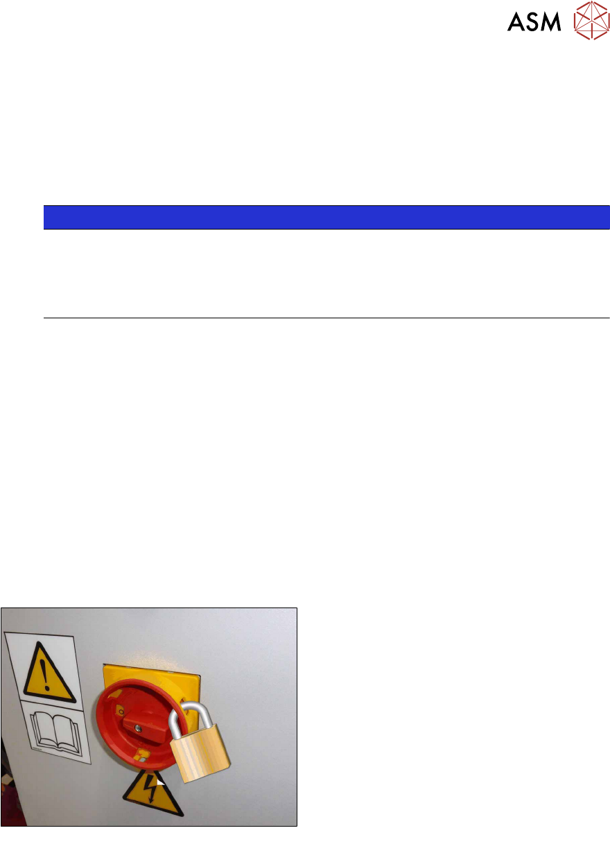
► Lock out the machine.
ð Attach a lock wherever possible:
Fig.4: Attaching a padlock to the main power switch
Secure Main Switch
► Secure the main switch with a padlock.
► Alternative: Attaching warning signs:
If a machine can be locked, it must be.
However, there are situations where energy isolating devices cannot accommodate locks. In
these cases, the energy isolating devices must be tagged to warn employees that the
machine is de-energized for servicing. The tag or label must be securely fastened, it must be
placed in a position visible to all and it may only be removed by the person who attached it.