00198150-02_SM_TX_en.pdf - 第241页
10 COT Insert 10.5 Replacing the Feeder Control Unit (FCU) Service Manual SIPLACE TX Series 06/2017 241 10.5 Replacing the Feeder Control Unit (FCU) Parts, Equipment and Tools ● X-FCU V2, TX-/X-Series [03096377-xx] Overv…
10 COT Insert
10.4 Replacing the 40-Fold Feeder Unlocking Device [03011582-xx]
240 Service Manual SIPLACE TX Series 06/2017
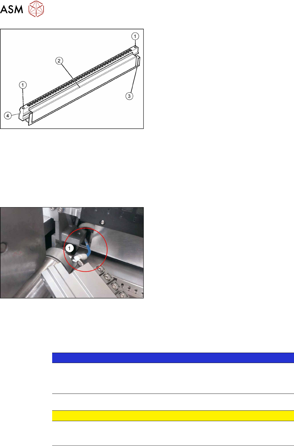
Fig.326: Feeder unlocking device
1. Two fastening screws
2. Complete feeder unlocking device
3. Connector for flat ribbon cable
4. Pneumatic connection
Removal
► Switch off the machine, disconnect it from the power supply and secure it to prevent
unauthorized reactivation. Observe the instructions in section 1.2 "Preparatory Work..." [}15].
► Unplug the flat ribbon cable from the connector.
► Remove the two fastening screws.
► Pull the flat ribbon cable out of the side of the connector. You may have to lift the feeder un-
locking device slightly to do this.
Fig.327: Pneumatic connection
► Lift the feeder unlocking device up and off and
pull the pneumatic connection(1)off.
Installation
Follow the removal instructions in reverse order for installation. Also observe the following instruc-
tions:
► Reconnect the system to the electrical and compressed air systems.
NOTICE
Pneumatic connection
You might find it advisable to remove the cover on the back of the COTi. This gives the
compressed air hose more room to be moved. In certain circumstances, the COT insert
may need to be loosened and pulled out slightly to the front.
► Carefully press the feeder unlocking device towards the back and insert the fastening screws.
CAUTION
Do not pinch the cable.
► Make sure not to pinch or damage the cables running at the back (connected to the
FCU).
10 COT Insert
10.5 Replacing the Feeder Control Unit (FCU)
Service Manual SIPLACE TX Series 06/2017 241
10.5 Replacing the Feeder Control Unit (FCU)
Parts, Equipment and Tools
●
X-FCU V2, TX-/X-Series [03096377-xx]
Overview
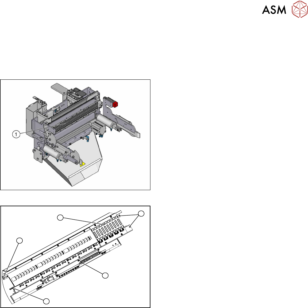
Fig.328: FCU on COTi
1. Feeder control unit
The feeder control unit is installed at the locations in
the COTi.
3
3
1
3
2
Fig.329: FCU Overview
1. Complete FCU
2. Terminal strip
3. Fixing screws of the FCU
Depending on the version, there will be four or six
screws.
10 COT Insert
10.5 Replacing the Feeder Control Unit (FCU)
242 Service Manual SIPLACE TX Series 06/2017
Removal
► Switch off the machine, disconnect it from the power supply and secure it to prevent
unauthorized reactivation. Observe the instructions in section 1.2 "Preparatory Work..." [}15].
► Dismantle the feeder unlock device (see 10.4 "Replacing the 40-Fold Feeder Unlocking
Device [03011582-xx]" [}239]).
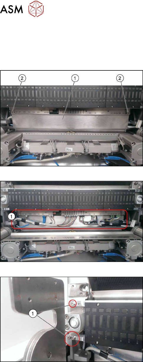
Fig.330: FCU Cover Plate
► Remove the two fixing screws(2) of the FCU
cover plate(1).
Fig.331: Connections
► Unplug all electrical connections from the ter-
minal strip of the FCU.
Fig.332: Fixing Screws
► Remove the fixing screws of the FCU(1) on both
sides.
Depending on the version, there will be four or six
screws.
► Carefully lever the FCU out of the locating pins.
► Remove the earth terminal.