00198150-02_SM_TX_en.pdf - 第154页
7 Conveyor 7.4 Width Adjustment 154 Service Manual SIPLACE TX Series 06/2017 Belt Tension Lane 1 (shorter): Toothed belt Brecoflex 5+-0.1 AT3/1509 [03121586‑xx] 25 +/- 2 Hz Lane 2 (longer): Toothed belt Brecoflex 5+-0.1 …
7 Conveyor
7.4 Width Adjustment
Service Manual SIPLACE TX Series 06/2017 153
7.4 Width Adjustment
7.4.1 Replacing the Toothed Belt (Width Adjustment) [03087325-xx]
Parts, equipment and tools
●
Lane 1 (shorter): Toothed belt Brecoflex 5+-0.1 AT3/1509 [03121586‑xx]
●
Lane 2 (longer): Toothed belt Brecoflex 5+-0.1 AT3/1701 [03121584‑xx]
●
Belt tension measuring device [00326015‑xx]
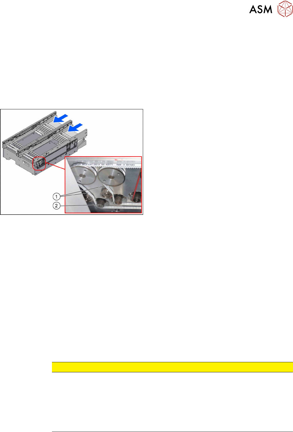
Overview
Fig.206: Toothed belts
1. Toothed belts for width adjustment
2. Width adjustment motor
Removal
► Use the software or manually move the conveyor rail into a position which allows you best ac-
cess.
– To move the conveyor rail manually, pull the toothed belt of the width adjustment unit.
► Switch off the machine, disconnect it from the power supply and secure it to prevent
unauthorized reactivation. Observe the instructions in section 1.2 "Preparatory Work..." [}15].
► Move all gantries out of the transport area as far as possible at one side of the machine.
► You may have to move out the COTi to get access to the toothed belt. In this case follow the
instructions to move out the COTi.
Replacing the COTi Central Unit and Lifting Mechanics [}235]
► Unthread the toothed belt. If necessary loosen the three screws fastening the width adjust-
ment motor.
Installation
► Follow the removal instructions in reverse order for installation. Also observe the following in-
structions:
CAUTION
Installation instructions
► Make sure that the toothed belt is not folded or otherwise damaged.
► Carefully thread in the toothed belt. To do this, carefully lift the toothed belt a little (e.g.
with the shorter end of an Allen key).
► Make sure that the relevant conveyor side is not moved, to keep parallelism of the
conveyor sides.
► Set the correct belt tension (see below).
7 Conveyor
7.4 Width Adjustment
154 Service Manual SIPLACE TX Series 06/2017
Belt Tension
Lane 1 (shorter): Toothed belt Brecoflex 5+-0.1 AT3/1509 [03121586‑xx] 25 +/- 2 Hz
Lane 2 (longer): Toothed belt Brecoflex 5+-0.1 AT3/1701 [03121584‑xx] 21 +/- 2 Hz
See also
2 Replacing the COTi Central Unit and Lifting Mechanics [}235]
2 Setting the Tension of the Conveyor Toothed Belt [}159]
2 Replacing the COTi Central Unit and Lifting Mechanics [}235]
7.4.2 Replacing Clamping Unit [03121328-xx]
Parts, equipment and tools
● Clamping unit 4 assy M-C [03121328-xx]
● Tor
que screwdriver ESD 1.0-5.0 Nm [03078400-xx]
● Torque allen swap blade 2mm [00386136-xx]
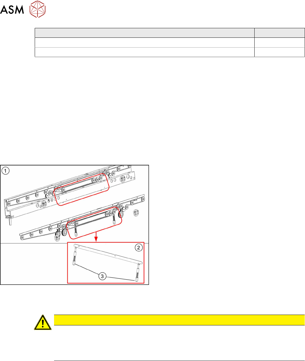
Overview
Fig.207: Clamping unit
1. Clamping unit on conveyor side
2. Clamping unit complete
3. Actuator
Removal
CAUTION
Small parts
► Take care not to lose any small parts.
► Take particular care not to let the screws fall into the conveyor wall when removing the
screws or clamping plate.
► Use the software or manually move the conveyor rail into a position which allows you best ac-
cess.
– To move the conveyor rail manually, pull the toothed belt of the width adjustment unit.
► Switch off the machine, disconnect it from the power supply and secure it to prevent
unauthorized reactivation. Observe the instructions in section 1.2 "Preparatory Work..." [}15].
► Move all gantries out of the transport area as far as possible at one side of the machine.
► Remove the lifting table plate to make room for removing the actuator later (see chapter 7.2.1
"Replacing the Lifting Table Plate [03114873-xx]" [}136]).
7 Conveyor
7.4 Width Adjustment
Service Manual SIPLACE TX Series 06/2017 155
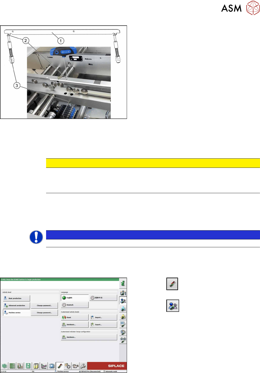
Fig.208: Removing clamping plate
► Insert the small pin or Allen key(3) to fix the actu-
ator.
► Remove the two screws(2) fastening clamping
plate(1).
First loosen one screw lightly, and then loosen
the other screw lightly.
► Remove inserted Allen key and remove the actu-
ator from bottom side.
►
Remove the clamping plate(1) with two fastening
screws carefully.
Installation
► Follow the removal instructions in reverse order for installation. Also observe the following in-
structions:
CAUTION
Installation instructions
► Tighten the fastening screws (2) with a torque of 1.45 Nm (NO loctite).
► Remove the pin (3).
7.4.3 Calibrating the Adjustment Unit
NOTICE
This chapter is valid for machines with dual conveyor (DC) only.
After completing all work to the width adjustment (adjustment unit, motor or belt of width adjust-
ment), you need to configure the adjustment unit before you configure the conveyor sides.
Procedure
Fig.209: Select operator level
► Click the
button to enter the Settings
menu.
► Click the
button to open the Check and set
user settings menu.
► Switch to operator level Machine service or bet-
ter.