00198150-02_SM_TX_en.pdf - 第110页
6 Gantries 6.3 Trailing Cable and Printed Circuit Boards 110 Service Manual SIPLACE TX Series 06/2017 Fig.134: Removing the upper cover ► Remove the four nuts at (2) and the four nuts at (3) on location1. Repeat for …
6 Gantries
6.3 Trailing Cable and Printed Circuit Boards
Service Manual SIPLACE TX Series 06/2017 109
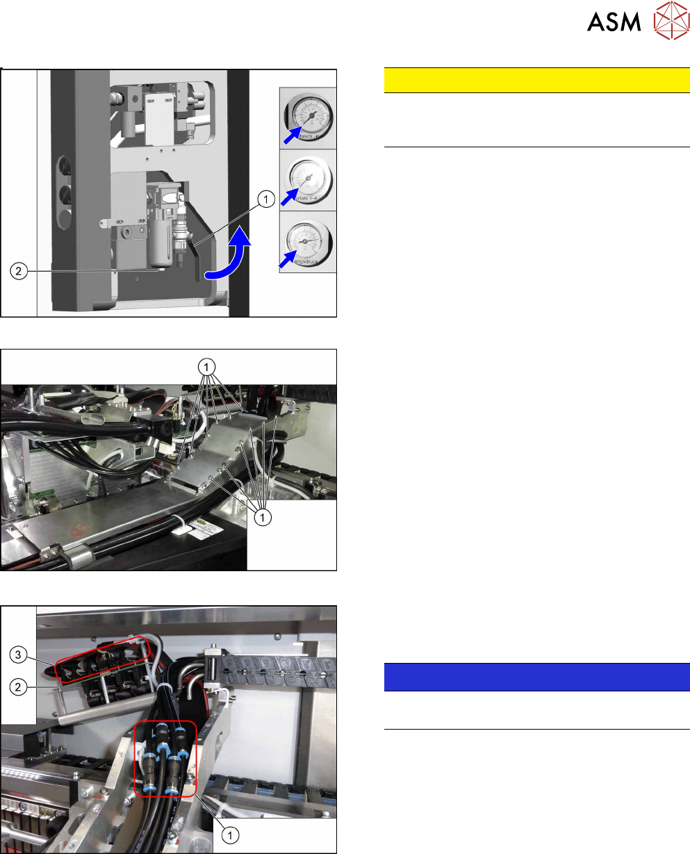
Fig.131: Disabling the compressed air supply
CAUTION!
Switch off the compressed air supply.
When working on the pneumatic system, always
switch off the compressed air supply.
.
► Push the lever (1) for the compressed air supply
back, until it is positioned horizontally.
► Open the screw (2) on the inlet filter to vent the
system. Hold a cloth underneath to capture any
escaping oil.
► All pressure gauges must be set to zero.
Fig.132: Cover
► Remove the twelve screws(1) and remove the
upper cover. These screws are secured with Loc-
tite241.
Fig.133: Hoses
► You might like to mark the positions of the hoses
on both sides of the couplings(1), so that these
can be easily assigned later on.
NOTICE!
Hose 1 usually is already marked.
Especially pay attention to hoses 1 and 2.
.
► Pull the hoses off the couplings.
► Mark the positions of the connectors(2) on the
gantry interface(3) so that these can be easily
assigned later on.
► Pull the connector off the gantry interface and un-
thread the cable.
6 Gantries
6.3 Trailing Cable and Printed Circuit Boards
110 Service Manual SIPLACE TX Series 06/2017
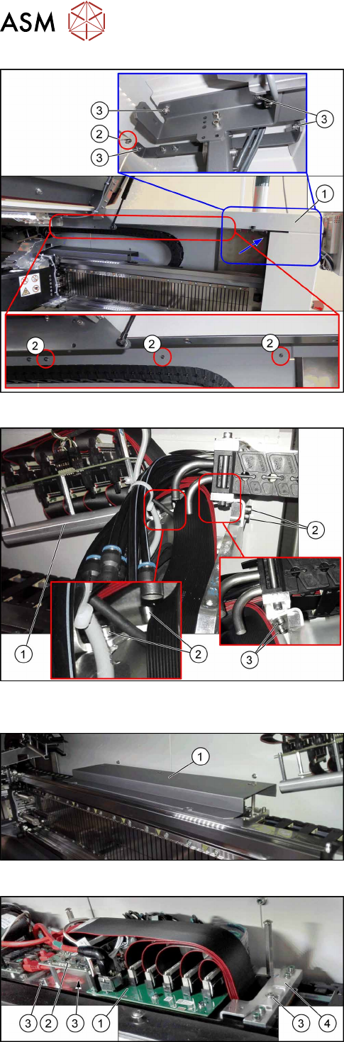
Fig.134: Removing the upper cover
► Remove the four nuts at(2) and the four nuts
at(3) on location1. Repeat for location2.
Ask for the help of a second person for the next step.
► Lift up the cover(1).
Fig.135: Trailing cable console
► Remove the four screws(2) fastening the trailing
cable console(1).
► Lift up the trailing cable console to have access
to the two screws (3) fastening the upper end of
the trailing cable.
► Remove the two screws(3).
Fig.136: Cover
► Remove the screws fastening the cover(1) on
the trailing cable interface and remove the cover.
Fig.137: Trailing cable interface and Vision base interface
► Mark the cables coming from the trailing cable on
the trailing cable interface(1) and Vision base in-
terface(2) to make clear assignment easier later
on.
► Unplug the cables coming from the trailing cable
at the trailing cable interface.
► Remove the three screws(3) fastening the con-
sole(4).
6 Gantries
6.3 Trailing Cable and Printed Circuit Boards
Service Manual SIPLACE TX Series 06/2017 111
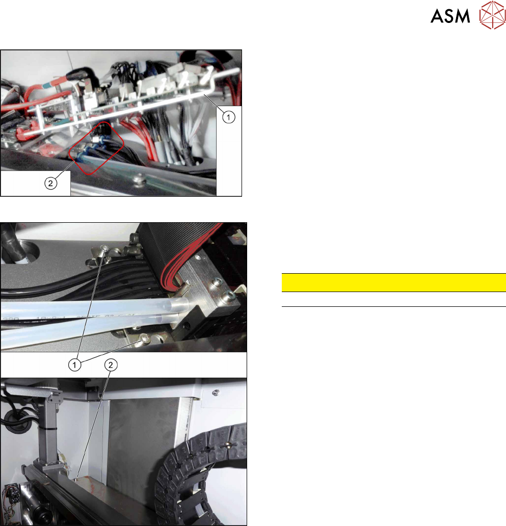
Fig.138: Hoses
► Lift up the console(1) to get access to the
hoses(2).
► Pull the hoses off. You may want to mark their po-
sitions for easier replacement later on.
Fig.139: Trailing cable fastening screws
The trailing cable is fastened with three screws.
► Loosen the two screws(1).
► Loosen the screw(2).
CAUTION!
Do not open any other screws.
.
► Carefully remove the trailing cable from the machine.