00198150-02_SM_TX_en.pdf - 第208页
8 Placement Heads and Stationary Cameras 8.3 Replacing the SIPLACE CPP/M Head 208 Service Manual SIPLACE TX Series 06/2017 Installation ► Follow the removal instructions in reverse order for installation. Also observe th…
8 Placement Heads and Stationary Cameras
8.3 Replacing the SIPLACE CPP/M Head
Service Manual SIPLACE TX Series 06/2017 207
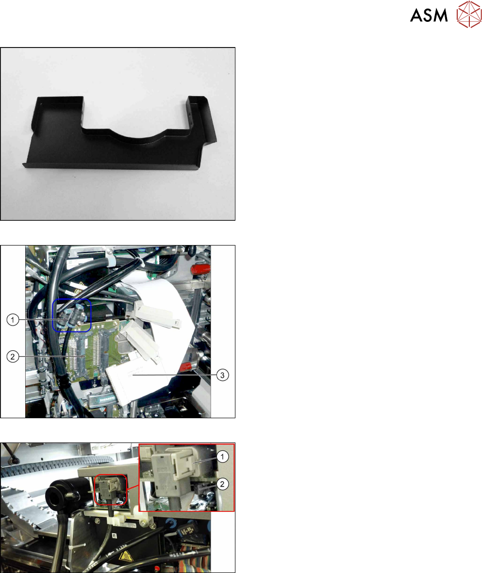
Fig.281: Component sensor protective cap
► Fit the protective cap onto the component sensor
for the placement head.
Fig.282: Connections
► Unplug the pneumatic connections(1) from the
placement head. You may want to mark the posi-
tions to make clear assignment easier later on.
► Disconnect the flat ribbon cables(3) from the in-
termediate distributor(2).
Fig.283: Cables
► Push the button(1) to unplug the cable, open the
clamps on both sides of connector to unplug the
flat ribbon cable(2).
► Remove all four screws fastening the head with a long Torx screwdriver.
► Carefully lift the head out of the locating pins on the head plate and from the hook.
► Placing the head into the head transport box
8 Placement Heads and Stationary Cameras
8.3 Replacing the SIPLACE CPP/M Head
208 Service Manual SIPLACE TX Series 06/2017
Installation
► Follow the removal instructions in reverse order for installation. Also observe the following in-
structions:
CAUTION
Installation instructions
► If you replace the head without the component camera, you will need to fit the old
camera onto the new head. Read the service manual for your placement head for
more information.
► Observe the correct installation height of the head (top or bottom position, see 8.3.1
"Preparing the CPP Head for the Installation Height" [}209])!
► Make sure that the assembly position on the head plate is correct.
► Tighten the four fastening screws with a torque of 2.7Nm.
► Make sure that the flat ribbon cable is run correctly to the head adapter (see below).
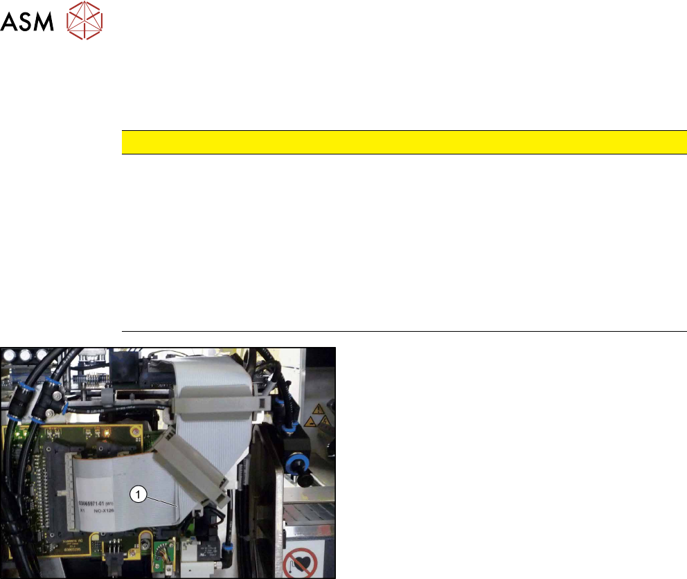
Fig.284: Flat ribbon cable
Correct running of flat ribbon cable to head ad-
apter
► Make sure that the flat ribbon cable is run cor-
rectly to the head adapter. In particular, the
cables must lie inside one another at the 90 de-
grees turn(1) and not on top of one another, oth-
erwise the connections on the head adapter
could be easily confused.
8 Placement Heads and Stationary Cameras
8.3 Replacing the SIPLACE CPP/M Head
Service Manual SIPLACE TX Series 06/2017 209
8.3.1 Preparing the CPP Head for the Installation Height
CAUTION
Different heights
The placement head can be installed at two different heights. CPP_L corresponds to a
component height of sixmm. CPP_H corresponds to a component height of 11.5mm.
If the CPP head is used in a placement area with stationary camera, TwinHead or JTF, it
may only be used in the upper position.
Overview
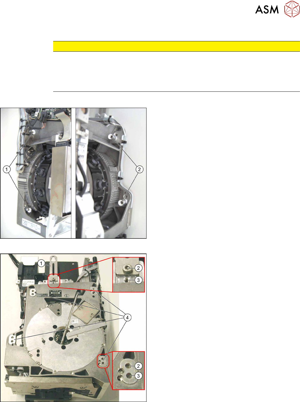
Fig.285: Fastening screws
1. Fastening screws on the left side
2. Fastening screws on the right side
This diagram shows the fastening screws in the "head
at top" position.
Fig.286: CPP head positions
1. Holding bracket
2. "Head at bottom" position
3. "Head at top" position
4. Fixture holes with bushings