00198150-02_SM_TX_en.pdf - 第161页
7 Conveyor 7.5 Conveyor Belt, Belt Drive and Hexagonal Shaft Service Manual SIPLACE TX Series 06/2017 161 7.5.3 Replacing the Idler Pulley [03092899Sxx] Parts, equipment and tools Select the required idler pulley: ● Idle…
7 Conveyor
7.5 Conveyor Belt, Belt Drive and Hexagonal Shaft
160 Service Manual SIPLACE TX Series 06/2017
► Check the belt tension at the relevant measuring point.
► If the belt tension is not correct, adjust the movable idler pulley.
CAUTION
Do not let the T groove nut fall into the conveyor wall!
► Do not remove the movable idler pulley completely, to make sure that the grooved nut
does not fall into the conveyor wall.
► Repeat the measurement four times.
See also
2 Replacing the COTi Central Unit and Lifting Mechanics [}235]
7.5.2.2 Calculating the Belt Tension
NOTICE
For conveyor belt only
This calculation only applies to the conveyor belts of SIPLACE TX machines.
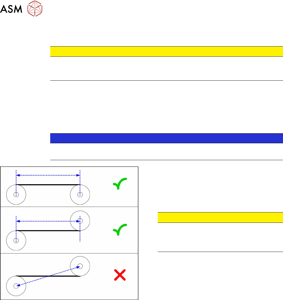
Fig.217: Measuring the distance
► Define the two idler pulleys between which you
want to set the belt tension. If possible, do not
use the movable idler pulleys.
► Measure the distance between the two idler pul-
leys parallel to the conveyor belt. (see dia-
gram)
CAUTION!
Note that it is not always possible to simply
measure the distance between the idler pulleys
from center to center.
.
► Calculate the belt tension using the following for-
mula:
(15000 / idler pulley spacing [mm]) [Hz]
The permissible tolerance is always plus/minus 10%
of the calculated value.
Example
Distance between the idler pulleys: 235mm
Calculation:
15000 / 235 = 64 (rounded, exactly 63.829…)
10 % von 63.829… = 6 (rounded, exactly 6.3829…)
Result:
Belt tension: 64 +/- 6 Hz
7 Conveyor
7.5 Conveyor Belt, Belt Drive and Hexagonal Shaft
Service Manual SIPLACE TX Series 06/2017 161
7.5.3 Replacing the Idler Pulley [03092899Sxx]
Parts, equipment and tools
Select the required idler pulley:
●
Idler pulley 20x5 M-C assy [03121206‑xx]
●
Idler pulley 20x2.5 M-C assy [03121201‑xx]
You also need the following:
●
Magnet lifter, if needed or tweezers and adhesive tape
●
Torque screwdriver ESD 0.4 - 1.0 Nm [00386253‑xx]
●
Bit holder for TorqueVario screwdriver [03078706-xx]
●
Bit, size 4
●
Measuring scale, if needed
●
Belt tension measuring device [00326015‑xx]
Overview
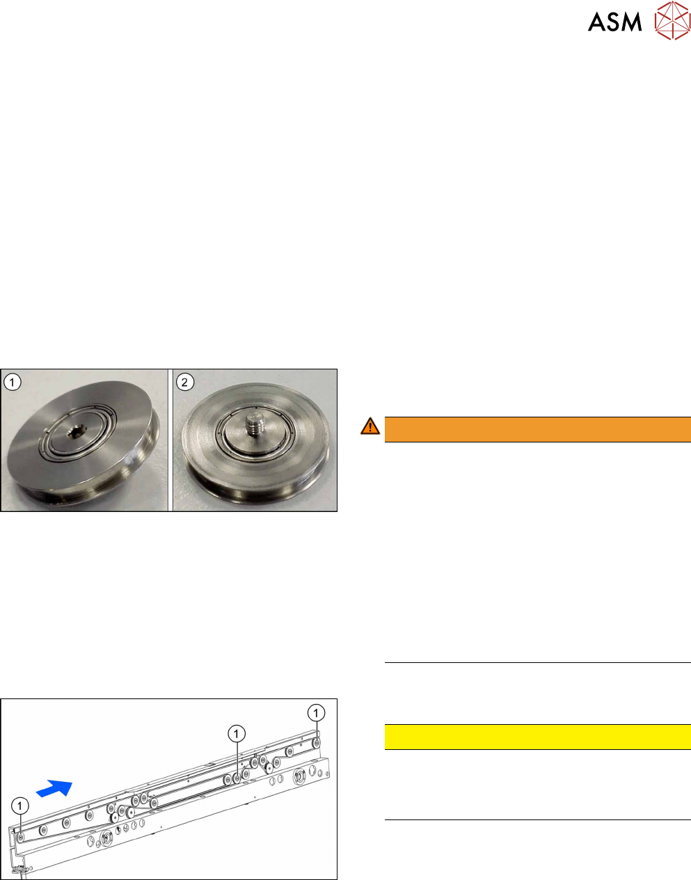
Fig.218: Idler pulley
1. Idler pulley front side
2. Idler pulley back side
WARNING!
Torque
Tighten the fastening screw with a torque of 0.58
Nm. Make sure that you do not tighten the
screws too much. This could cause irreparable
damage to the conveyor!
The corresponding thread is only in 1.5 to 2mm
thick plates and could be damaged if you use a
torque which is too high.
For this reason, avoid using screws which are
too short. Use a measuring scale to check, if
needed!
This could cause irreparable damage to the con-
veyor!
.
Fig.219: Movable idler pulleys
1. Movable idler pulleys
CAUTION!
Fix the T slot nut!
When replacing a movable idler pulley, fix the T
slot nut to the inner side of the conveyor wall
(see description below).
.
7 Conveyor
7.5 Conveyor Belt, Belt Drive and Hexagonal Shaft
162 Service Manual SIPLACE TX Series 06/2017
Removal
CAUTION
Toothed belt
► Make sure that the toothed belt is not folded or otherwise damaged.
► Use the software or manually move the conveyor rail into a position which allows you best ac-
cess.
– To move the conveyor rail manually, pull the toothed belt of the width adjustment unit.
NOTICE
Replacing a movable idler pulley
► If you are replacing a movable idler pulley you will have to move the conveyor side to
get access to the T slot nut (see below).
► Switch off the machine, disconnect it from the power supply and secure it to prevent
unauthorized reactivation. Observe the instructions in section 1.2 "Preparatory Work..." [}15].
► Move all gantries out of the transport area as far as possible at one side of the machine.
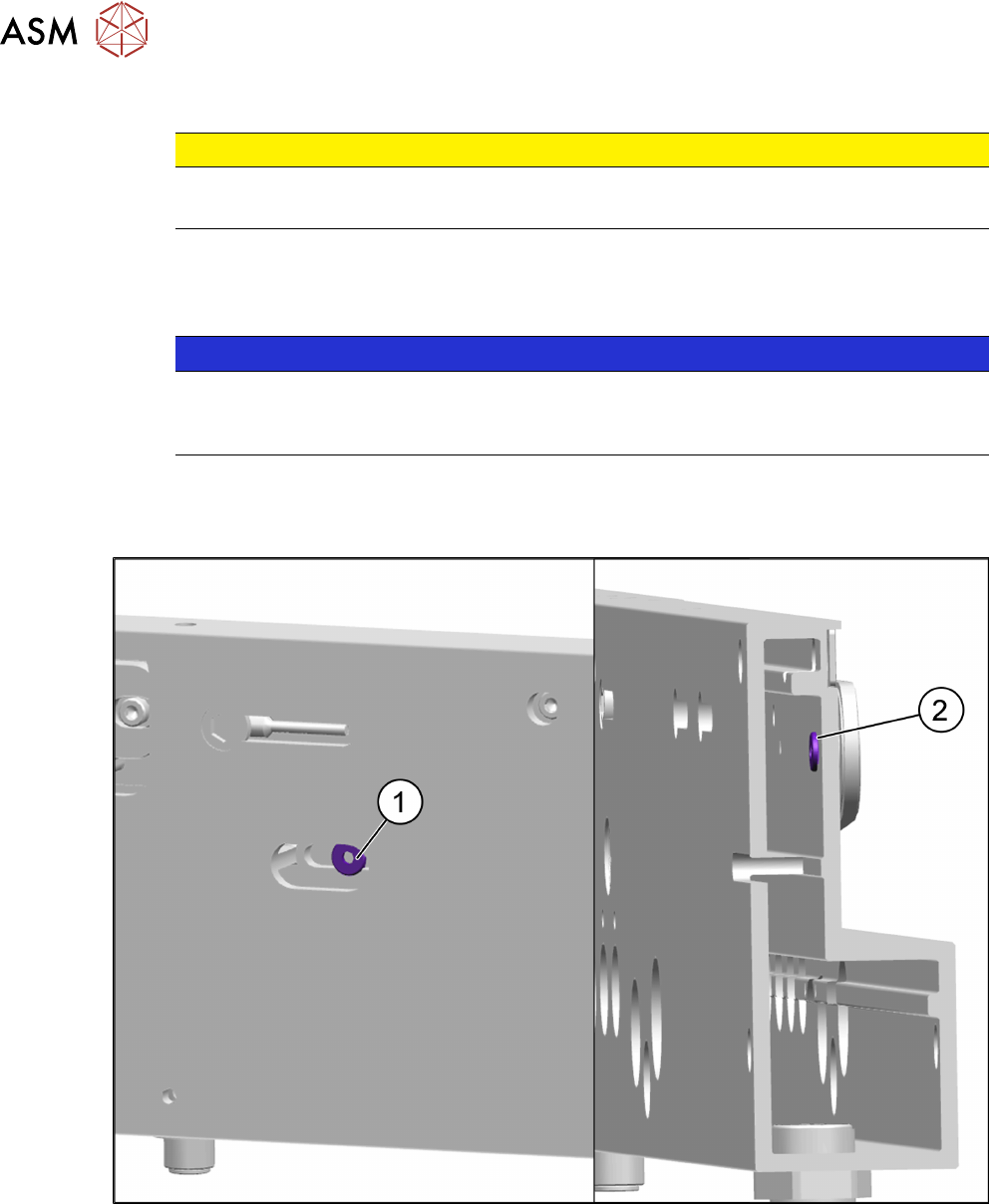
Fig.220: T slot nuts in conveyor side