00198150-02_SM_TX_en.pdf - 第129页
6 Gantries 6.4 MHCU, Boards and Camera Service Manual SIPLACE TX Series 06/2017 129 6.4.9 Anticrash Function Fig.168: Example of the anticrash function sequence in placement area 1 NOTICE MGCU, MHCU The MGCU and the MHC…
6 Gantries
6.4 MHCU, Boards and Camera
128 Service Manual SIPLACE TX Series 06/2017
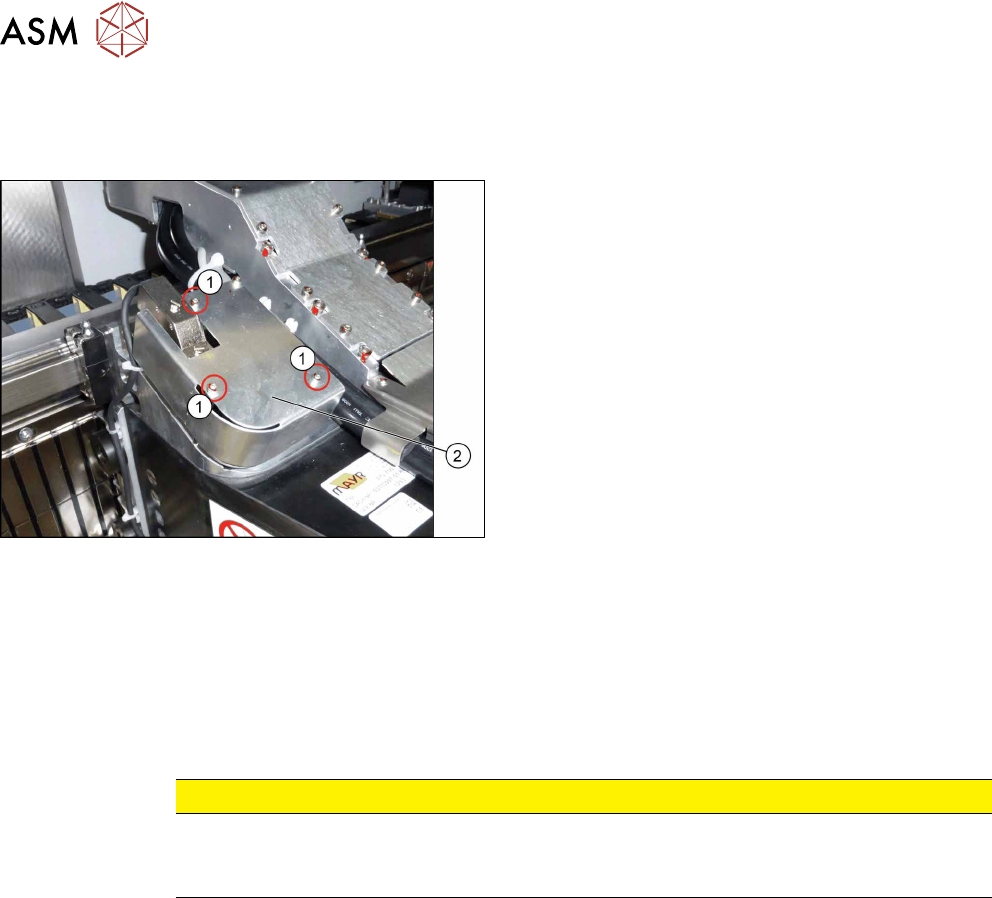
Removal
► Switch off the machine, disconnect it from the power supply and secure it to prevent
unauthorized reactivation. Observe the instructions in section 1.2 "Preparatory Work..." [}15].
► Remove the three fastening screws(1).
► Remove the cover(2) over the board.
► Unplug all electrical connections to the board (see above). You may want to mark the posi-
tions of these connections to make clear assignment easier later on.
► Remove the four fastening screws (see above).
► Remove the "sensor module universal".
Installation
► Follow the removal instructions in reverse order for installation. Also observe the following in-
structions:
CAUTION
Installation instructions
► Perform a embedded software download (see 6.4.11 "eSW Download (SW
70x)" [}130]).
6.4.8 Error "Gantry Crash"
A “gantry crash” error is established by calculating the position difference and speed difference for
both axes. A gantry crash error is signaled via the MGCUs and the CAN Bus. After the "gantry
crash" error message has been issued, both gantries need to be referenced.
6 Gantries
6.4 MHCU, Boards and Camera
Service Manual SIPLACE TX Series 06/2017 129
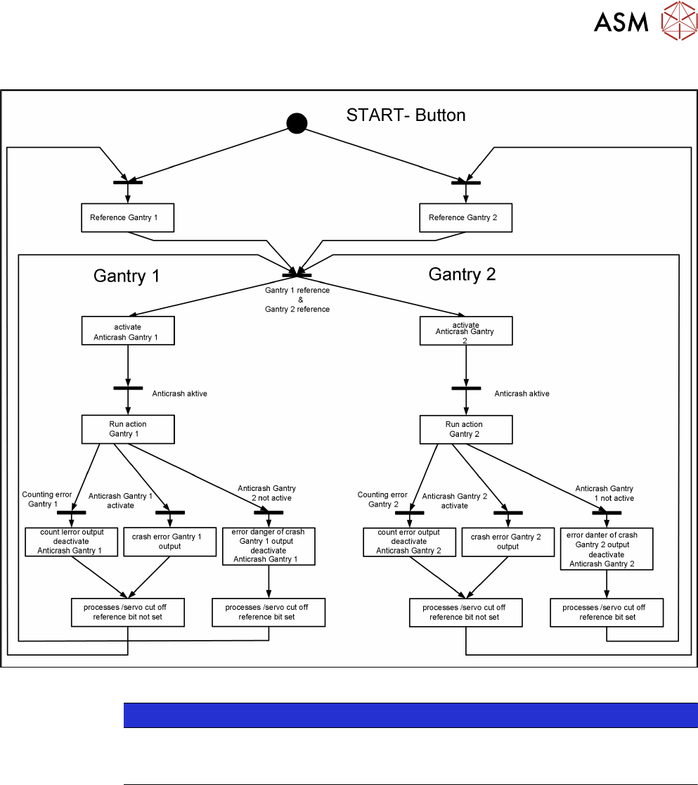
6.4.9 Anticrash Function
Fig.168: Example of the anticrash function sequence in placement area 1
NOTICE
MGCU, MHCU
The MGCU and the MHCU consist of a control module (axis card) and a power module
(servo).
6.4.10 Count Error
If the MGCU detects a "fatal count error", the axis concerned will be released and the anticrash
function disabled. The other axis is informed of this in the status information and will also disable
the anticrash function. The released axis now needs to be referenced again.
After this, the anticrash function will be re-enabled for both axes.
6 Gantries
6.4 MHCU, Boards and Camera
130 Service Manual SIPLACE TX Series 06/2017
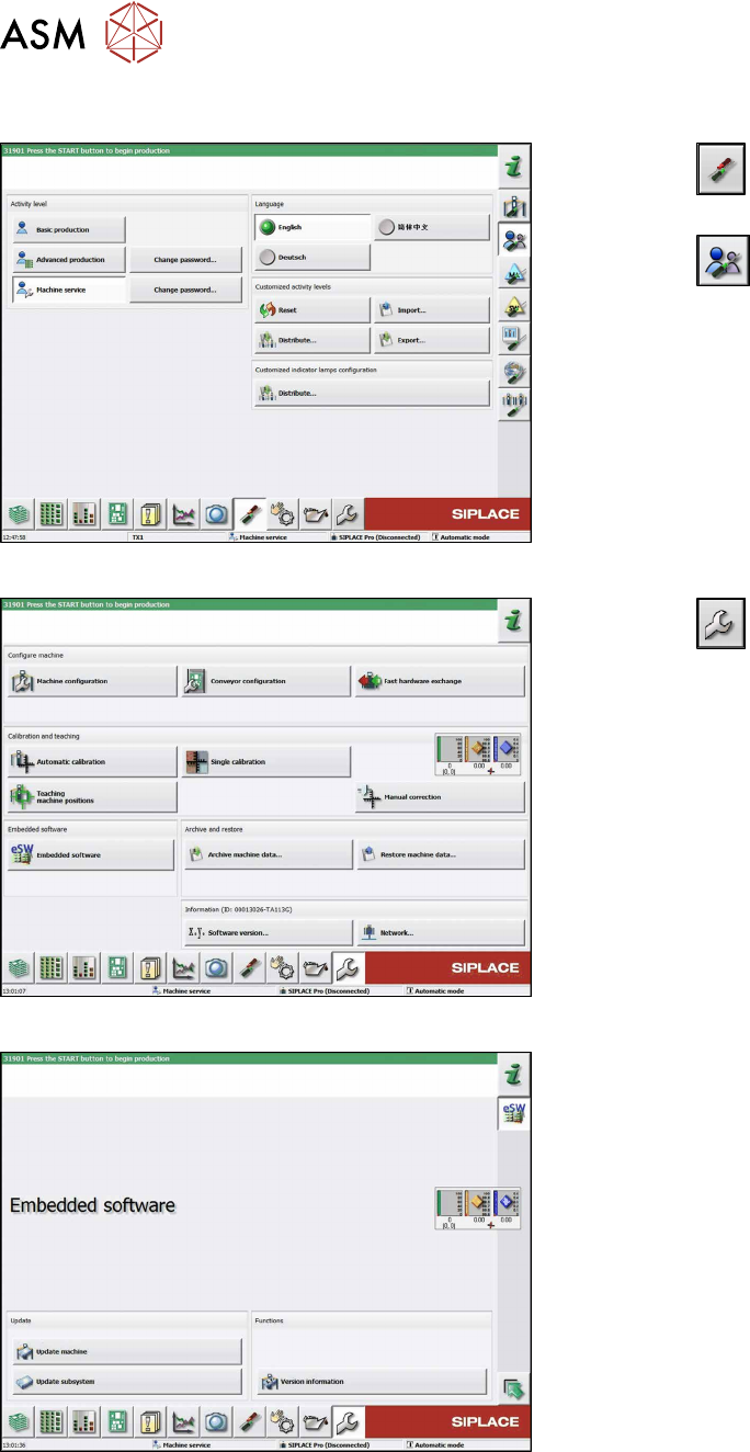
6.4.11 eSW Download (SW 70x)
Fig.169: Select operator level
► Click the
button to enter the Settings
menu.
► Click the
button to open the Check and set
user settings menu.
► Switch to operator level Machine service or bet-
ter.
Fig.170: Service menu
► Click the
button to enter the Service menu.
► Click on the Embedded software button.
Fig.171: Embedded software menu
Select the required function:
► Click on Update machine… to check the entire
machine and to perform an eSW download for
multiple subsystems (see next picture).
► Click on Update subsystem… to select and
check one subsystem and to perform an eSW
download.
► Click on the button Version information…, to
view all versions of the subsystems, BIOS, ap-
plication 1/2/3/5.