00198150-02_SM_TX_en.pdf - 第301页
14 JEDEC Tray Feeder 14.1 SIPLACE JTF-ML Service Manual SIPLACE TX Series 06/2017 301 Fig.428: Disconnecting X1 ► Disconnect the X1 plug. Fig.429: Disconnecting the X3 ► Perform steps (1) to (3) to unfold the interloc…
14 JEDEC Tray Feeder
14.1 SIPLACE JTF-ML
300 Service Manual SIPLACE TX Series 06/2017
14.1.2 Replacing the SIPLACE JTF ML Adapter [03114835-xx]
Parts, equipment and tools
●
SIPLACE JTF-ML adapter assembly [03114835-xx]
Removal / installation
► For more information, please read the user manual "SIPLACE JTF-ML – JEDEC Tray
Feeder" [00198140‑xx].
14.1.3 Replacing the SIPLACE JTF-ML FDK [03110417‑xx]
Parts, equipment and tools
●
SIPLACE JTF-ML FDK U1 COTi (COT insert) [03110417-xx]
Removal
► For more information, please read the user manual "SIPLACE JTF-ML – JEDEC Tray
Feeder" [00198140‑xx].
14.1.4 Replacing the Control Board X Adapter [03050293-xx]
Parts, equipment and tools
●
PCB Control Board X Adapter [03050293-xx]
●
Antistatic tweezers (e.g. [00377393‑xx] or [00377394‑xx])
Overview
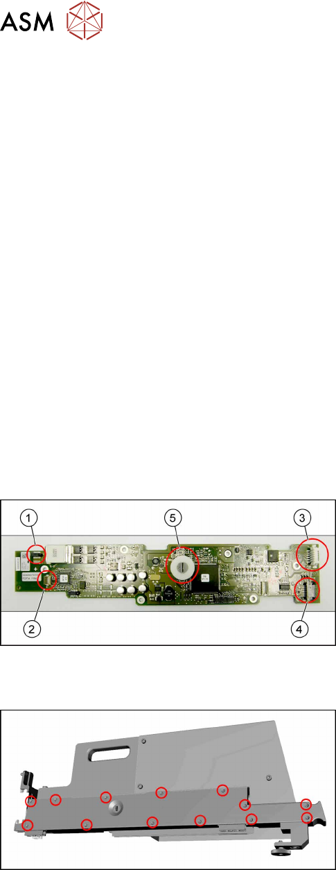
Fig.426: Control board X adapter overview
1. Power connector X1 from EDIF
2. Signal connector X3 from EDIF
3. Output X4 to Lemosa connector (SIPLACE JTF-
ML)
4. Connection X17 to control panel
5. Switches for addressing and communication pro-
tocol
Removal
Fig.427: Removing the cover
► Remove all cross-head screws marked in the pic-
ture.
► Remove the cover from the SIPLACE JTF-ML
Adapter.
Now you have access to the control board X adapter [03050293‑xx].
14 JEDEC Tray Feeder
14.1 SIPLACE JTF-ML
Service Manual SIPLACE TX Series 06/2017 301
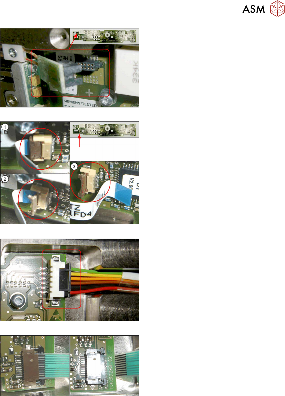
Fig.428: Disconnecting X1
► Disconnect the X1 plug.
Fig.429: Disconnecting the X3
► Perform steps (1) to(3) to unfold the interlock
and disconnect the X3 plug.
Fig.430: Disconnecting the X4
► Disconnect the X4 plug.
Fig.431: Disconnecting the X17
► Open the interlock and disconnect X17.
Use antistatic tweezers for opening the interlock.
14 JEDEC Tray Feeder
14.1 SIPLACE JTF-ML
302 Service Manual SIPLACE TX Series 06/2017
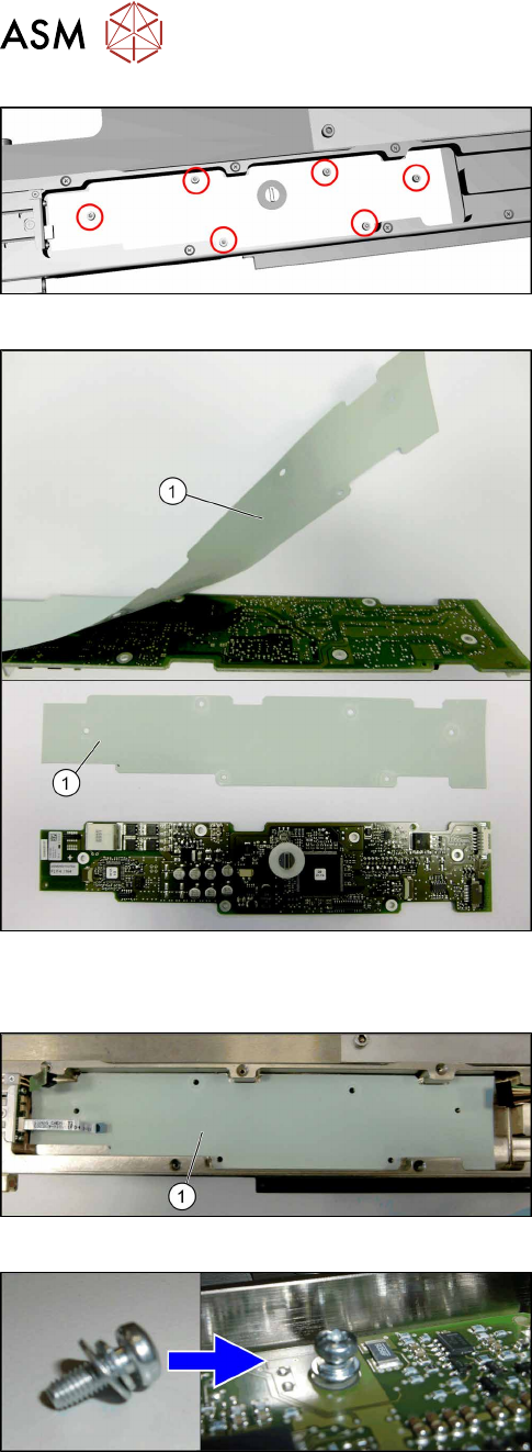
Fig.432: Removing the control board X adapter
► Remove the six screws (torxT10) fastening the
control board X adapter.
► Remove the control board X adapter.
Fig.433: Insulation layer
► Take care of the insulation layer(1) on the back-
side of the control board X adapter.
The isolation layer will be reused with the new
control board X adapter.
► Carefully remove the insulation layer from the
control board X adapter.
Installation
Fig.434: Positioning the insulation layer
► Place the old insulation layer in position.
Center the holes in the insulation layer to the
screw holes.
► Place the new control board X adapter in posi-
tion.
Center the holes in the control board to the screw
holes.
Fig.435: Fitting the control board X adapter
► Fix the control board X adapter with six fastening
screws (torx T10) hand-tight.
Take care to use all washers and circlips cor-
rectly.