00198150-02_SM_TX_en.pdf - 第203页
8 Placement Heads and Stationary Cameras 8.2 Replacing the SIPLACE C&P20 P/M2 Head Service Manual SIPLACE TX Series 06/2017 203 Overview Fig.275: C&P20P 1. Holding circuit connection 2. Intermediate distributor…
8 Placement Heads and Stationary Cameras
8.2 Replacing the SIPLACE C&P20 P/M2 Head
202 Service Manual SIPLACE TX Series 06/2017
8.2 Replacing the SIPLACE C&P20 P/M2 Head
NOTICE
Vacuum test
► If required, perform a vacuum test before removing the placement head.
Read the "Service manual Vacuum test at C&P placement head" [DE+EN:
00196101‑xx] for this.
NOTICE
Fast Head Exchange (FHE)
► Observe the instructions in section 8.1 "Fast Head Exchange" [}197] when exchan-
ging a head.
Parts, equipment and tools
●
C&P20 P placement head [03091157-xx] (without camera)
●
C&P20 M2 placement head [03125907Sxx] (without camera)
NOTICE
Vacuum pump/compressed air operation
As a spare part, the head is prepared for vacuum pump operation.
► Convert the placement head for compressed air operation using the "Hold-circuit com-
plete/C&P20" [03005123Sxx] kit.
●
Torx screwdriver ESD 1.0-5.0 Nm [03078400-xx]
●
Bit holder for TorqueVario screwdriver [03078706-xx]
●
Extension/straight TX20 [03073256-xx]
Fig.274: Component sensor protective cap
[03092400‑xx]
●
Component sensor protective cap
[03092400‑xx]
●
Calibration tool version SST23 [03034148-
xx]
For additional work to the placement head:
●
Head mount [03056231‑xx]
●
Service manual "SIPLACE C&P20P head" [DE:00197489‑xx] [EN:00197490‑xx]
8 Placement Heads and Stationary Cameras
8.2 Replacing the SIPLACE C&P20 P/M2 Head
Service Manual SIPLACE TX Series 06/2017 203
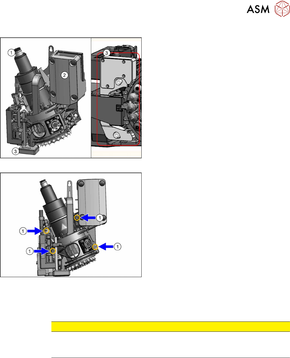
Overview
Fig.275: C&P20P
1. Holding circuit connection
2. Intermediate distributor board (behind the cover)
3. Component sensor
Fig.276: Fastening screws
1. Four fastening screws (yellow marks)
Removal
► Switch off the machine, disconnect it from the power supply and secure it to prevent
unauthorized reactivation. Observe the instructions in section 1.2 "Preparatory Work..." [}15].
CAUTION
Take great care when dismantling the placement head!
The component sensor prisms, underneath the placement head, could be damaged.
► Never place the placement head down on the component sensor.
► Fit the protective cap onto the component sensor for the placement head.
8 Placement Heads and Stationary Cameras
8.2 Replacing the SIPLACE C&P20 P/M2 Head
204 Service Manual SIPLACE TX Series 06/2017
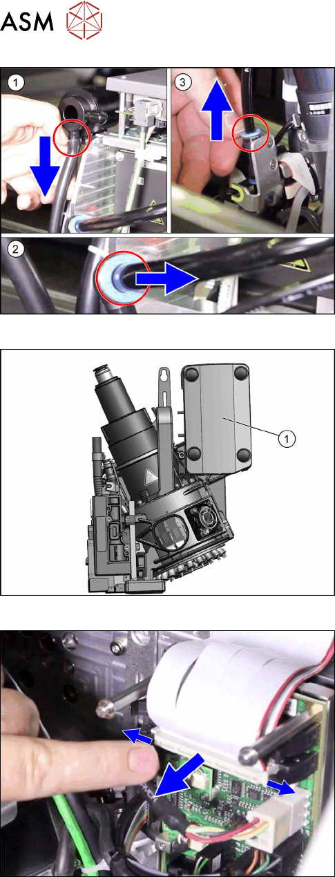
Fig.277: Pneumatic connections
► Disconnect the pneumatic connections(1) to(3)
from the placement head.
Fig.278: Cover on intermediate distributor board
► Remove the cover(1).
► Unplug the ribbon cables between the placement
head and the head adapter.