00198150-02_SM_TX_en.pdf - 第113页
6 Gantries 6.4 MHCU, Boards and Camera Service Manual SIPLACE TX Series 06/2017 113 6.4 MHCU, Boards and Camera 6.4.1 Gantries - MHCU, Boards and Camera - Overview Fig.141: MHCU, boards and camera 1. Head adapter 6.4.2 …
6 Gantries
6.3 Trailing Cable and Printed Circuit Boards
112 Service Manual SIPLACE TX Series 06/2017
Installation
► Installation is performed by following the above instructions in the reverse order. Also observe
the following instructions:
CAUTION
Always handle the trailing cable with care
► If a vacuum pump is fitted, also observe the relevant assembly instructions
[00196845‑xx].
► Always handle the new trailing cable with care.
► You might need to enlist the help of a second person.
► Make sure that the flat ribbon cable and the pneumatic hoses are not rubbed against
any parts or folded. Look out for sharp edges.
► Prepare the trailing cable. Place the old and new trailing cables next to one another
and match the length of the new trailing cable hose to the old one.
► If you use the new holder, you will need to dismantle all attached items (boards etc.)
from the old holder and attach them to the new holder.
► If hose ends were damaged during removal, cut these with hose cutters.
► Clean the trailing cable contact surface on the machine base with a dry cloth.
► Carefully insert the new trailing cable into the prescribed position. Make sure you do
not fold or twist the trailing cable.
► Check that the power track chain runs parallel to the machine base. Move the gantry
back and forth.
► If it is difficult to push the hoses onto the tubes, moisten these first with white spirits or
isopropanol.
► Secure screws with Loctite 241 (see below).
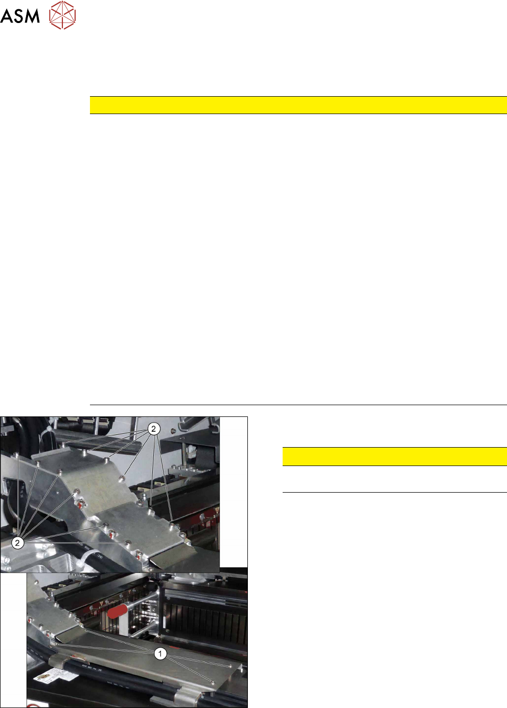
Fig.140: Covers
► Secure the screws(2) of the upper cover with
Loctite 241.
CAUTION!
Do not secure the screws(1) of the lower
cover with Loctite.
.
6 Gantries
6.4 MHCU, Boards and Camera
Service Manual SIPLACE TX Series 06/2017 113
6.4 MHCU, Boards and Camera
6.4.1 Gantries - MHCU, Boards and Camera - Overview
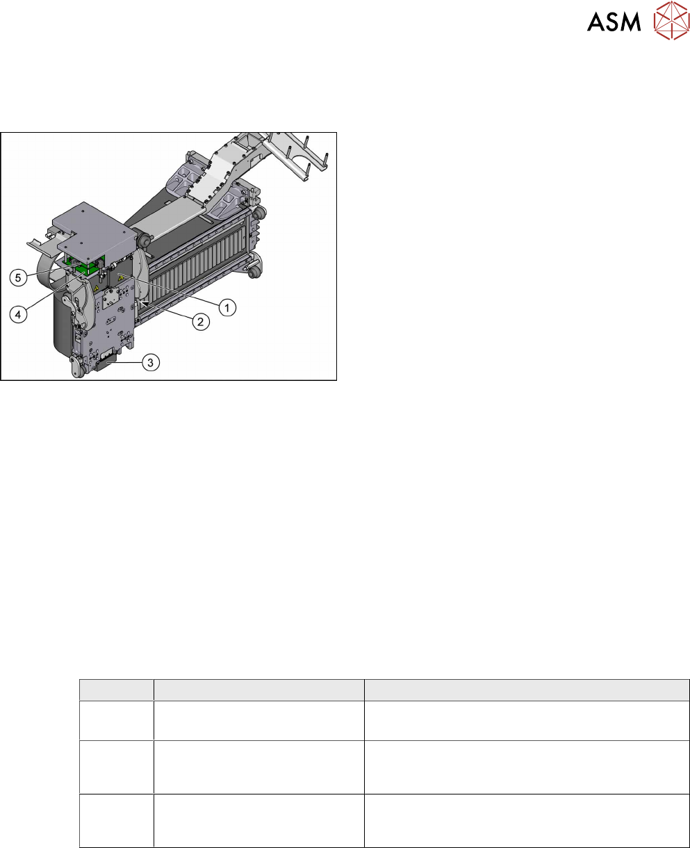
Fig.141: MHCU, boards and camera
1. Head adapter
6.4.2 "Replacing the Head Adapter for the
MHCU" [}113]
2. Gantry temperature sensor
6.4.6 "Replacing the Gantry Temperature
Sensor" [}125]
3. PCB camera
Replacing the PCB Camera
4. Head interface
6.4.4 "Replacing the Head Interface" [}120]
5. Vision Head Interface (VHI)
●
6.4.8 "Error "Gantry Crash"" [}128]
●
6.4.9 "Anticrash Function" [}129]
●
6.4.10 "Count Error" [}129]
●
6.4.11 "eSW Download (SW 70x)" [}130]
See also
2 Replacing the Vision Head Interface (VHI) [03115454-xx] [}117]
6.4.2 Replacing the Head Adapter for the MHCU
Parts, equipment and tools
The following spare parts can be replaced:
●
MHCU assembly, compatible [03090990Sxx]
●
MHCU assembly [03109668‑xx]
●
PCB / X base adapter C&P [03045647Sxx] from FS08
●
Module / X base adapter TWIN [03062201Sxx]
Head Adapter Number of MHCU, base adapters
CPP Module X base adapter C&P
[03071420-xx]
1x MHCU [03090990Sxx] from FS04
1x PCB / X base adapter C&P [03045647Sxx]
C&P20P Module X base adapter C&P 20
P
[03109399-xx]
1x MHCU [03090990Sxx] from FS04
1x PCB / X base adapter C&P [03045647Sxx]
Twin Head adapter Twin (M)HCU /
SX4
[03082096-xx]
2x MHCU [03090990Sxx] from FS04
1x module/ X base adapter TWIN [03062201Sxx]
Removal
► Switch off the machine, disconnect it from the power supply and secure it to prevent
unauthorized reactivation. Observe the instructions in section 1.2 "Preparatory Work..." [}15].
► You may need to dismantle the placement head for better access.
Replacing the SIPLACE CPP/M Head [}206]
Replacing the SIPLACE TwinHead [}210]
Replacing the SIPLACE C&P20 P/M2 Head [}202]
6 Gantries
6.4 MHCU, Boards and Camera
114 Service Manual SIPLACE TX Series 06/2017
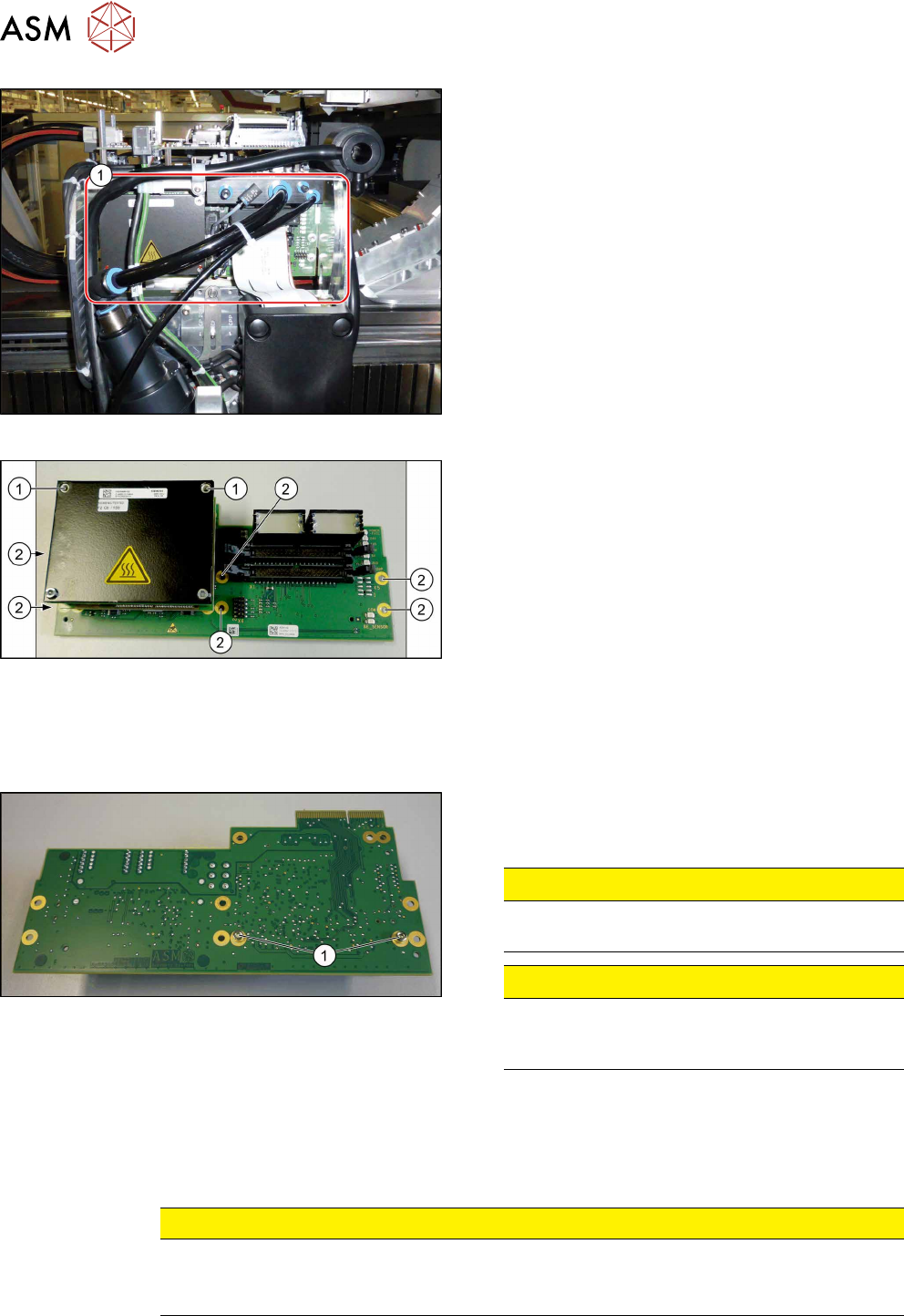
Fig.142: Head adapter MHCU (example of C&P20P shown)
► Unplug all electrical connections to the head ad-
apter(1). You may want to mark the position to
make clear assignment easier later on.
Fig.143: Head adapter
► Remove the screws(2) fastening the head ad-
apter.
► In addition, the head adapter is fastened with the
topmost two MHCU screws(1)in each case. Re-
move these two screws as well.
► Carefully pull the head adapter down and off.
The head adapter is connected to the head inter-
face from below via a press-fit connection.
Converting the MHCU
If you have ordered the base adapter without MHCU(s) you will have to convert the MHCU(s). Pro-
ceed as follows:
Fig.144: Head adapter backside
► Remove the two screws(1) fastening the MHCU
on the back of the board and carefully pull the
MHCU off the base adapter.
CAUTION!
Washers
Make sure that you do not lose the washers.
.
CAUTION!
Pins
Make sure that you do not damage the pins un-
der the MHCU.
.
► Only for Twin head: Repeat the procedure for the second MHCU.
Installation
► Follow the removal instructions in reverse order for installation. Also observe the following in-
structions:
CAUTION
Installation instructions
► Check the embedded software and perform a download if needed (see 6.4.11 "eSW
Download (SW 70x)" [}130]).
See also
2 Replacing the SIPLACE CPP/M Head [}206]
2 Replacing the SIPLACE TwinHead [}210]
2 Replacing the SIPLACE C&P20 P/M2 Head [}202]