00198150-02_SM_TX_en.pdf - 第65页
4 Electrical System and Control 4.2 Replacing the Control Computer BoxPC Service Manual SIPLACE TX Series 06/2017 65 4.2.1 Replacing the BoxPC 427x Overview Fig.67: Waste tape chute The BoxPC is located on location 1 be…
4 Electrical System and Control
4.2 Replacing the Control Computer BoxPC
64 Service Manual SIPLACE TX Series 06/2017
4.2 Replacing the Control Computer BoxPC
Parts, equipment and tools
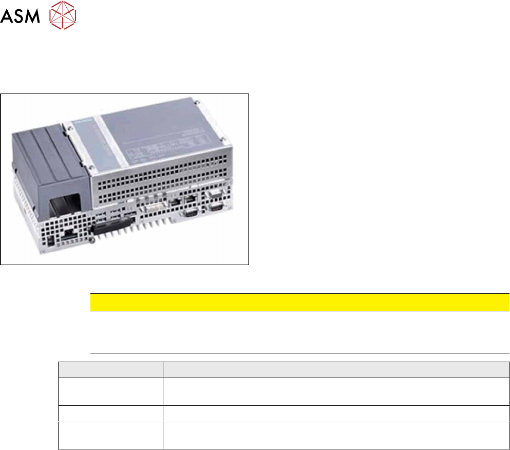
Fig.66: BoxPC 427D
●
Control computer BoxPC 427D processor i3
2xPCIe [03114177‑xx]
CAUTION
Additional hardware for the BoxPC
The BoxPC is supplied without the following parts. If required, these must be removed from
the old BoxPC and fitted in the new one or ordered as new parts:
BoxPC 427D
GigE interface
(cameras)
GigE Ethernet adapter PCI-E I350T2V2BLK [03115569‑xx]
RAM
See 4.3 "Replacing the RAM in the BoxPC" [}67].
Ethernet adapter If a 3D Coplan or a barcode scanner is installed, the "LAN card PCI Ex-
press 2x Gigabit LAN" [03118416-xx] is needed in addition.
●
Installation manual for Windows Embedded Standard 7 [00197737-xx]
4 Electrical System and Control
4.2 Replacing the Control Computer BoxPC
Service Manual SIPLACE TX Series 06/2017 65
4.2.1 Replacing the BoxPC 427x
Overview
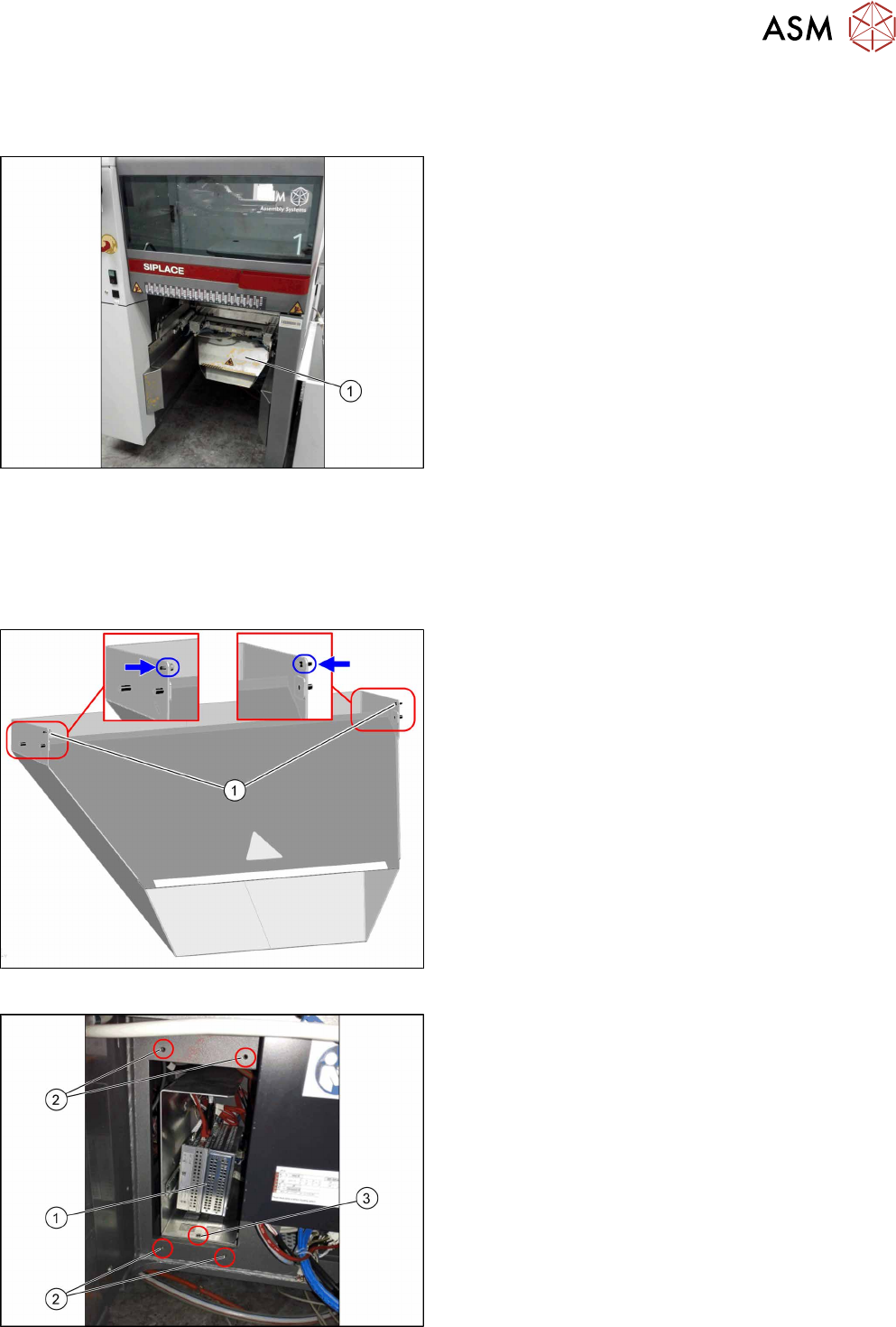
Fig.67: Waste tape chute
The BoxPC is located on location 1 behind the waste
tape chute(1).
Removal
► Backup the machine data.
► Switch off the machine, disconnect it from the power supply and secure it to prevent
unauthorized reactivation. Observe the instructions in section 1.2 "Preparatory Work..." [}15].
Fig.68: Waste tape chute
► Loosen the two safety screws(1) on the waste
tape chute and unhook the waste tape chute.
Fig.69: Fastening screws
► Remove the five fastening screws(2) fixing the
cover plate in front of the BoxPC(1).
► Remove the fastening screw(3) of the support
frame.
4 Electrical System and Control
4.2 Replacing the Control Computer BoxPC
66 Service Manual SIPLACE TX Series 06/2017
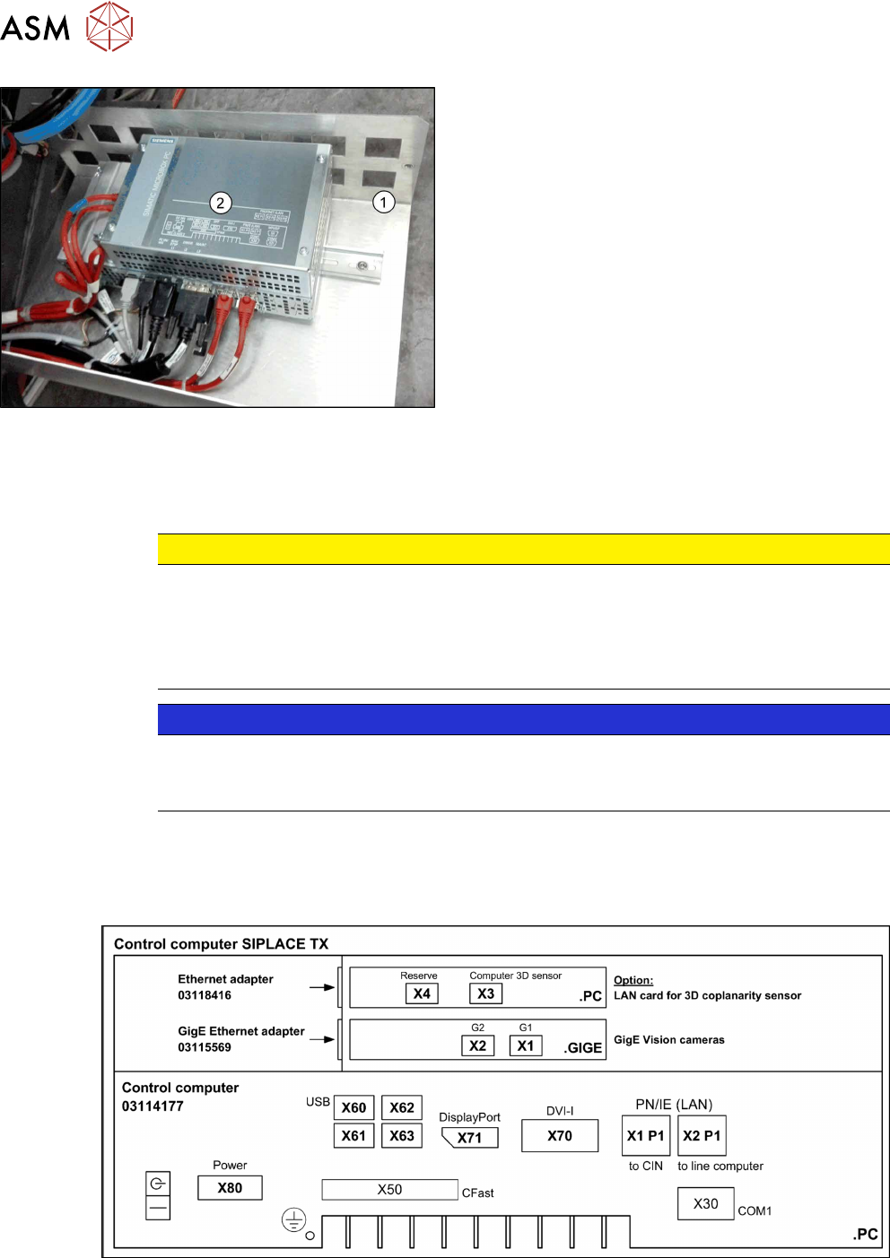
Fig.70: BoxPC on support frame
► Move the support frame(1) with the BoxPC(2)
out of the machine.
► Unplug all press-fit connections to the BoxPC.
You may want to mark their positions to make
clear assignment easier later on.
See also: Overview of Connections for BoxPC
427D
► Remove the BoxPC from the support frame.
Installation
► Follow the removal instructions in reverse order for installation. Also observe the following in-
structions:
CAUTION
Installation instructions
► If parts are missing in the new BoxPC (e.g. ethernet adapter, memory extension), take
these from the old BoxPC and use them in the new one (see corresponding chapters).
► The BoxPC needs to be installed and configured after it has been built in (see the fol-
lowing note).
NOTICE
Installing the BoxPC
► The BoxPC needs to be installed after it has been fitted. Read the installation guide
"Windows Embedded Standard 7" [00197366-xx].
See also
2 Replacing the Waste Tape Chute [03125182-xx] [}251]
4.2.2 Overview of Connections for BoxPC 427D
Fig.71: BoxPC 427D