00198150-02_SM_TX_en.pdf - 第165页
7 Conveyor 7.6 Fiber Optic Cable and Light Barriers Service Manual SIPLACE TX Series 06/2017 165 Removal ► Use the software or manually move the conveyor rail into a position which allows you best ac- cess. – To move the…
7 Conveyor
7.6 Fiber Optic Cable and Light Barriers
164 Service Manual SIPLACE TX Series 06/2017
7.6 Fiber Optic Cable and Light Barriers
7.6.1 Replacing the Laser Light Barrier for the Transmitter/Receiver
Parts, Equipment and Tools
●
Laser light barrier transmitter [03098280‑xx]
●
Laser light barrier receiver [03098281‑xx]
●
Flashlight, if needed
●
Magnet lifter, if needed
●
Tweezers, if needed
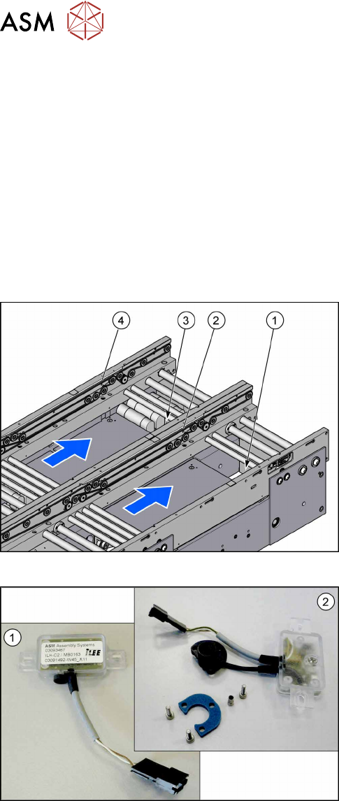
Overview
Fig.221: Transmitter and receiver
1. Transmitter PA (lane 1)
2. Receiver PA (lane 1)
3. Transmitter PA (lane 2)
4. Receiver PA (lane 2)
Fig.222: Transmitter and receiver
1. Receiver
2. Transmitter (incl. assembly material)
7 Conveyor
7.6 Fiber Optic Cable and Light Barriers
Service Manual SIPLACE TX Series 06/2017 165
Removal
► Use the software or manually move the conveyor rail into a position which allows you best ac-
cess.
– To move the conveyor rail manually, pull the toothed belt of the width adjustment unit.
► Switch off the machine, disconnect it from the power supply and secure it to prevent
unauthorized reactivation. Observe the instructions in section 1.2 "Preparatory Work..." [}15].
► Move all gantries out of the transport area as far as possible at one side of the machine.
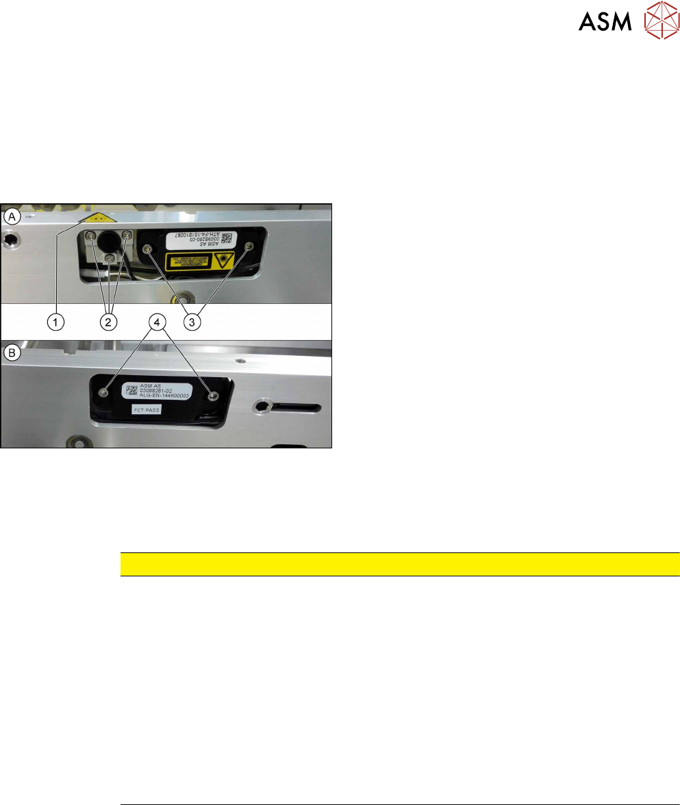
Fig.223: Removing transmitter and receiver
The transmitters are always near the laser warning la-
bels(1). The receivers are always on the opposite
sides.
► (A) Transmitter:
Remove the five fastening screws(2) and(3).
Make sure that no parts fall into the conveyor rail.
► (B) Receiver:
Remove the two fastening screws(4). Make sure
that no parts fall into the conveyor rail.
► Unplug the electrical connection.
Installation
► Follow the removal instructions in reverse order for installation. Also observe the following in-
structions:
CAUTION
Installation instructions
► Reconnect the transmitter/receiver before installation.
► Make sure that all the other cables in the conveyor rail are run under the transmitter/
receiver. There is a particular lack of space at the transmitters.
► Use the bushing for the bottom screw. This screw is used to fix the sensor.
The two upper screws are used to adjust the laser beam.
► The transmitters are fixed hand-tight with the lower screw and adjusted with the top
two screws.
► Check the setting for the transmitter/receiver and correct if necessary (see 7.6.5.1
"Setting the Fiber Optic Cable Sensor" [}176]).
► Teach the PCB sensors using the station software (see 7.10 "Teaching the PCB
Sensors (SW70x)" [}192]).
7 Conveyor
7.6 Fiber Optic Cable and Light Barriers
166 Service Manual SIPLACE TX Series 06/2017
7.6.2 Checking the Laser Light Barrier
Whenever the laser light barrier is dismantled, it then needs to be manually set again afterwards.
Check the setting as follows:
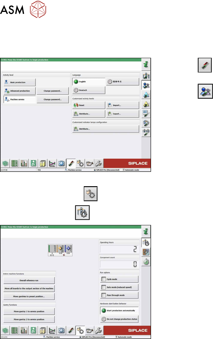
Fig.224: Select operator level
► Click the
button to enter the Settings
menu.
► Click the
button to open the Check and set
user settings menu.
► Switch to operator level Machine service or bet-
ter.
► Click on the
button, to switch over to the menu Check sensors and functions.
► Click the
button.
Fig.225: Safety mode
► Enable the button Safety mode (reduced
speed).