00198150-02_SM_TX_en.pdf - 第174页
7 Conveyor 7.6 Fiber Optic Cable and Light Barriers 174 Service Manual SIPLACE TX Series 06/2017 7.6.5 Replacing the Fiber Optic Cable Sensor Parts, equipment and tools ● Fiber optic sensor WLL180T-M pre-programmed SXa […
7 Conveyor
7.6 Fiber Optic Cable and Light Barriers
Service Manual SIPLACE TX Series 06/2017 173
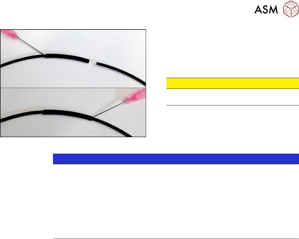
Fig.234: Repairing fiber optic cable
► Slide both ends of the fiber optic cable into the
repair hose until they touch each other.
► Use Loctite 406 on the repair hose.
Thus, the fiber optic cable is fixed in the hose.
The two ends of the fiber optic cable are not
glued to each other.
CAUTION!
Highly viscous instant glue
Use gloves and a dosage tip.
.
NOTICE
Installation instructions
► Check the setting for the transmitter / receiver and correct it if necessary (see Setting
and Correcting the Laser Light Barrier).
► Calibrate the sensors of the PCB conveyor.
► Check the display on the fiber optic sensor. The value shown must be over 100.
Check the value for various conveyor widths (red = output / green = input).
► Mark the optical system and the fiber optic cable at the fiber optic sensor with the glue
dot supplied. The glue dot indicates that the fiber optic cable has already been re-
paired and that a replacement is compulsory at the next defect.
See also
2 Replacing the Fiber Optic Cable Sensor [}174]
7 Conveyor
7.6 Fiber Optic Cable and Light Barriers
174 Service Manual SIPLACE TX Series 06/2017
7.6.5 Replacing the Fiber Optic Cable Sensor
Parts, equipment and tools
●
Fiber optic sensor WLL180T-M pre-programmed SXa [03093294-xx] (master) or
Fiber optic sensor WLL180T-F pre-programmed SXa [03093295-xx] (slave)
Overview
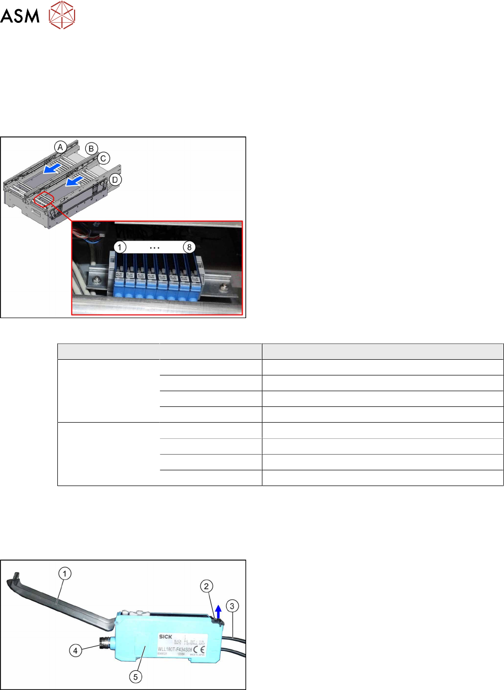
Fig.235: Fiber optic cable sensors
The fiber optic cable sensors are located at location 2
under the lifting table plate.
The sensors (1) to (8) for the input conveyor, place-
ment area (second sensor as option) and output area.
The receiver is always at the top of the sensors and
the transmitter at the bottom.
Conveyor lane Designation Location
Lane 1 1 (master) Input belt
2 (slave) Placement area
3 (slave) Second sensor as option
4 (slave) Output belt
Lane 2 5 (slave) Input belt
6 (slave) Placement area
7 (slave) Second sensor as option
8 (slave) Output belt
The master synchronizes the slaves to prevent any mutual interference. This is conducted via a
side connection to the neighboring sensor. For this reason, do not simply lift the sensors up and off
the strip.
Each sensor has two fiber optic cables connected (transmitter/receiver), which belong to the same
conveyor belt (segment).
Fig.236: Fiber optic cable sensor
1. Cover
2. Locking the fiber optic cables
top = open
bottom = closed
3. Fiber optic cable
4. Electrical connection
5. Electrical connection to neighboring receiver (un-
der the plastic cover)
7 Conveyor
7.6 Fiber Optic Cable and Light Barriers
Service Manual SIPLACE TX Series 06/2017 175
Removal
CAUTION
Do not bend the fiber optic cable
► Make sure you do not bend the fiber optic cable. Otherwise the cable will become
cloudy and no longer transmit the signal properly.
► Use the software or manually move the conveyor rail into a position which allows you best ac-
cess.
– To move the conveyor rail manually, pull the toothed belt of the width adjustment unit.
► Switch off the machine, disconnect it from the power supply and secure it to prevent
unauthorized reactivation. Observe the instructions in section 1.2 "Preparatory Work..." [}15].
► Move all gantries out of the transport area as far as possible at one side of the machine.
► Dismantle the cover on the fiber optic sensors.
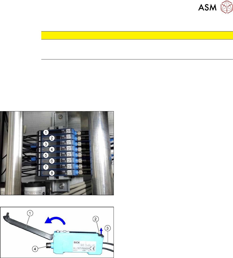
Fig.237: Fiber optic cable sensors
The individual sensors are connected to one another
via a small terminal strip.
Dismantle the row after the sensors, beginning with (8)
(lane2, output belt) until you have reached the sensor
to be replaced. Perform the following tasks at each
sensor:
► Open the cover(1) on the sensor.
► Open the lock(2) on the fiber optic cables(3) and
then pull off the fiber optic cables. You might like
to mark their positions to make clear assignment
easier later on.
► Disconnect from the power supply(4). You may
want to mark the position, to make clear assign-
ment easier later on.
► Pull the sensor slightly away from the other
sensors, to loosen the electrical connection to the
neighboring sensor. Now you can pull the sensor
up and off the strip.
► Repeat these steps if needed for any other
sensors.