00198150-02_SM_TX_en.pdf - 第289页
13 Docking Station for Component Trolley 13.3 Replacing the Microfuse [03033387-xx] Service Manual SIPLACE TX Series 06/2017 289 13.3 Replacing the Microfuse [03033387-xx] Parts, equipment and tools ● Microfuse [03033387…
13 Docking Station for Component Trolley
13.2 Replacing the Power Pack [03121806-xx]
288 Service Manual SIPLACE TX Series 06/2017
13.2 Replacing the Power Pack [03121806-xx]
NOTICE
Observe the technical information
► Observe the technical information "Power pack for docking station for component trol-
ley SIPLACE X [116933] and SX [116965] has been discontinued" [DE: TI2015-04D07]
[EN: TI2015-04E07].
Parts, equipment and tools
●
Switching power supply RSP-500-27 [03121806‑xx] (replaces: [03025938‑xx])
●
Detailed circuit diagrams folder for SIPLACE TX-Series (up to no. 499) [DE+EN: 00197933-
xx]
●
Detailed circuit diagrams folder for SIPLACE TX-Series (from no. 500) [DE+EN: 00198274-xx]
Removal / installation
DANGER
Switch off the voltage supply
► Press the ON/OFF button to switch off and disconnect the power supply.
4
3
1
3
2
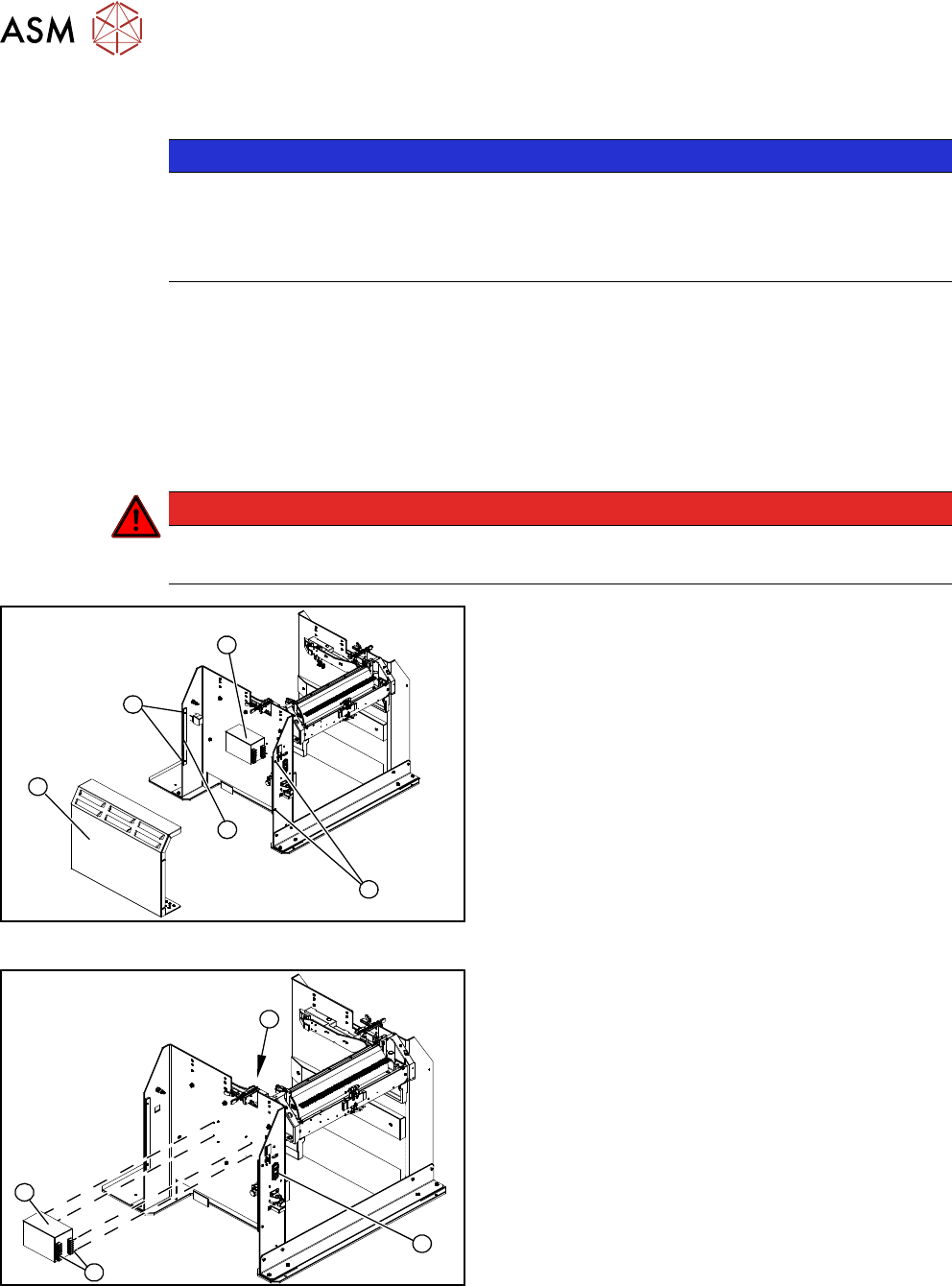
Fig.406: Removing the cover
1. Operation cover
2. Bar for clamping the cover
3. Four fastening screws
4. Power pack
► Remove the four screws (3) fastening the cover
(1). The cover is clamped in place with the help
of the bar(2).
► Pull the cover out of the docking station.
► Take care not to damage the earth connection.
4
3
1
2
Fig.407: Removing the power pack
► Disconnect all electrical connections(4) to the
power pack(3). You may want to mark their posi-
tions to make clear assignment easier later on.
► Remove the four screws (2) fastening the power
pack on the inside of the docking station.
► Connect all cables and fit the new power pack.
► Press the ON/OFF button(1) to switch on.
► Set the output voltage of the power pack at ter-
minals nine and twelve:
– Standard (without BulkFeeder):
26.8 V (+/- 0.5 V)
– When using the BulkFeeders the output
voltage is set permanently to
28.0V(+/‑0.5V).
► Refit the cover.
13 Docking Station for Component Trolley
13.3 Replacing the Microfuse [03033387-xx]
Service Manual SIPLACE TX Series 06/2017 289
13.3 Replacing the Microfuse [03033387-xx]
Parts, equipment and tools
●
Microfuse [03033387-xx]
Overview
1
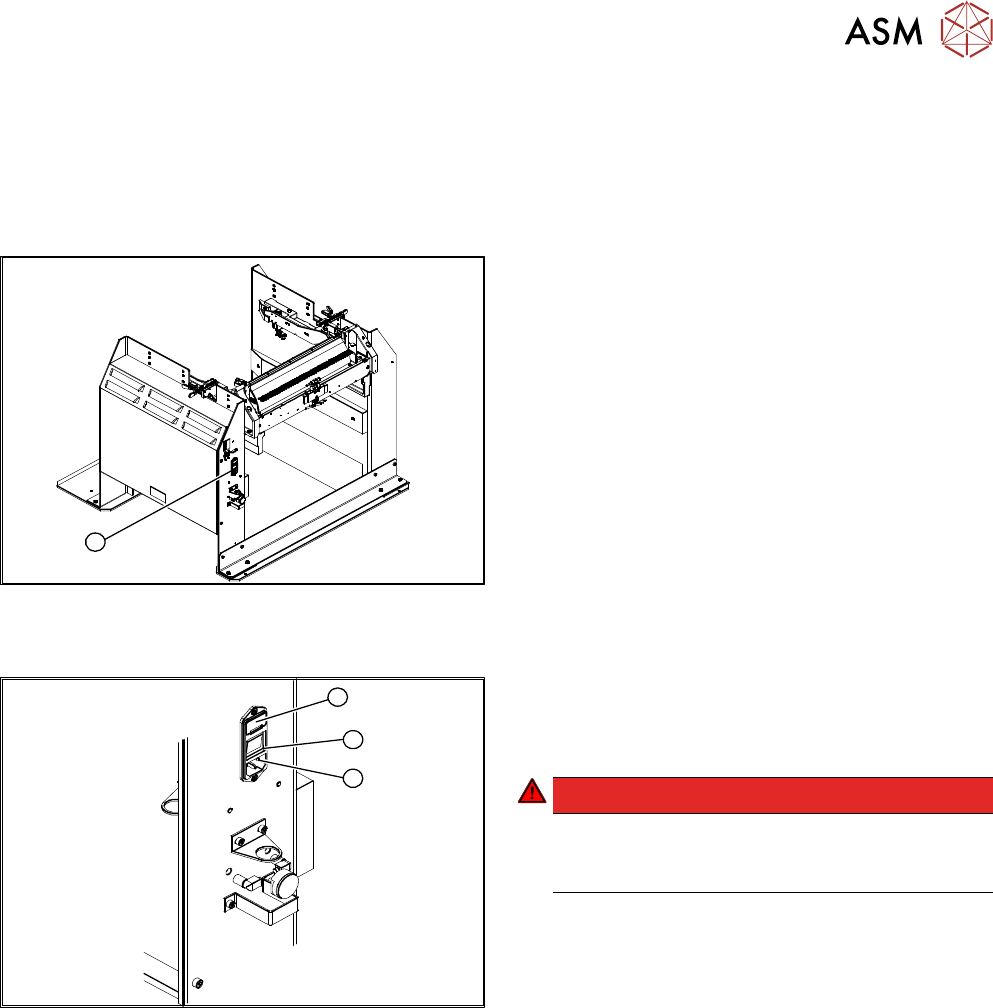
Fig.408: Microfuse on docking station
1. Position of microfuse (T 8.0 A)
Replacing the micro switch
1
3
2
Fig.409: Replacing the Micro Switch
1. Cover on the microfuse (T8.0A)
2. ON / OFF switch
3. Power supply plug
DANGER!
Switch off the voltage supply
Press the ON/OFF button (2) to switch off and
then unplug the power supply (3).
.
► Open the cover (1) on the microfuse.
► Remove the microfuse.
► Insert the new microfuse and close the cover (1).
► Connect the connection cable (3) and press the ON/OFF button to switch on (2).
13 Docking Station for Component Trolley
13.4 Replacing the Locking Unit Short-Stroke Cylinder [03034831-xx]
290 Service Manual SIPLACE TX Series 06/2017
13.4 Replacing the Locking Unit Short-Stroke Cylinder
[03034831-xx]
Parts, equipment and tools
●
Short-stroke cylinder [03034831-xx]
Overview
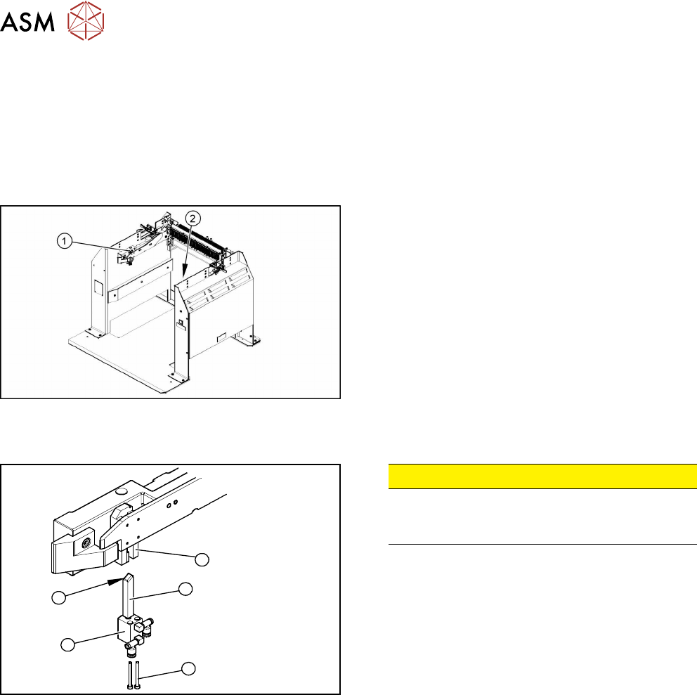
Fig.410: Locking unit left and right
1. Installation position of left locking unit
2. Installation position of right locking unit
Removal
5
1
4
3
2
Fig.411: Removing the locking unit
CAUTION!
Risk of injury
Risk of injury when disconnecting pressurized
compressed air lines.
.
► Switch off the compressed air supply.
► Remove the pneumatic connections on the short-
stroke cylinder.
► Remove the two screws (1) fastening the short-
stroke cylinder (2).
► Pull the short-stroke cylinder (2) and the locking
slider(3) downwards and out of the guidance
block(5).
► Unscrew the locking slider (3) from the short-
stroke cylinder (2).
Installation
► Install the locking slider (3) on the new short-stroke cylinder (2).
► Clean the locking sliders (3) and the guidance block (5) with a clean, lint-free cloth and lubric-
ate both slightly with Unisilikon.
► Move the locking slider (3) into the guidance block, so that the beveled side (4) is pointing to
the front (in the direction of travel). This is important when moving the component trolley in.
► Fit the short-stroke cylinder with the two fastening screws.
► Reconnect to the compressed air supply.
► Switch the compressed air supply on and check that the left and right locking sliders move out
at the same time.
► If necessary, adjust the throttle valve (6) on the short-stroke cylinder.