00198150-02_SM_TX_en.pdf - 第253页
11 Cutter 11.3 Replacing the Cutter on the COT Insert [03066690-xx] Service Manual SIPLACE TX Series 06/2017 253 Fig.346: Cutter fastening screws ► Remove the four fastening screws (1) on the cut- ter mount. Fig.347: …
11 Cutter
11.3 Replacing the Cutter on the COT Insert [03066690-xx]
252 Service Manual SIPLACE TX Series 06/2017
11.3 Replacing the Cutter on the COT Insert [03066690-xx]
Parts, equipment and tools
●
Cutter, pneumatic SIPLACE HF/X-Series [03066690-xx]
●
If needed, mounting plate [00312731-xx]
Alternatively: two large parallel clamps and a sturdy table with even surface to clamp down
the dismantled cutter
Overview
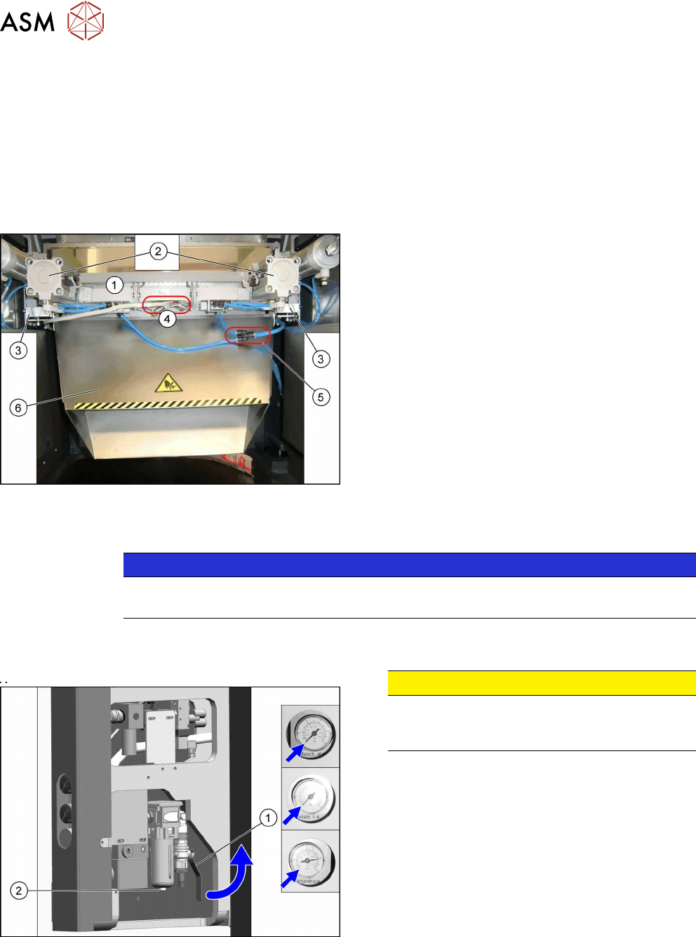
Fig.344: Cutter overview
1. Cutter
2. Short-stroke cylinder
3. Support plate on cutter
4. Electrical connections
5. Main air supply
6. Waste tape chute
Removal
NOTICE
COT insert
The cutter can be removed without dismantling the COT insert.
► Switch off the machine, disconnect it from the power supply and secure it to prevent
unauthorized reactivation. Observe the instructions in section 1.2 "Preparatory Work..." [}15].
Fig.345: Disabling the compressed air supply
CAUTION!
Switch off the compressed air supply.
When working on the pneumatic system, always
switch off the compressed air supply.
.
► Push the lever (1) for the compressed air supply
back, until it is positioned horizontally.
► Open the screw (2) on the inlet filter to vent the
system. Hold a cloth underneath to capture any
escaping oil.
► All pressure gauges must be set to zero.
► Remove the waste tape chute (see 11.2 "Replacing the Waste Tape Chute
[03125182-xx]" [}251]).
► Unplug all electrical connections and cut all cable ties along this cable.
► Unplug the main air supply and cut all cable ties along this tubing.
11 Cutter
11.3 Replacing the Cutter on the COT Insert [03066690-xx]
Service Manual SIPLACE TX Series 06/2017 253
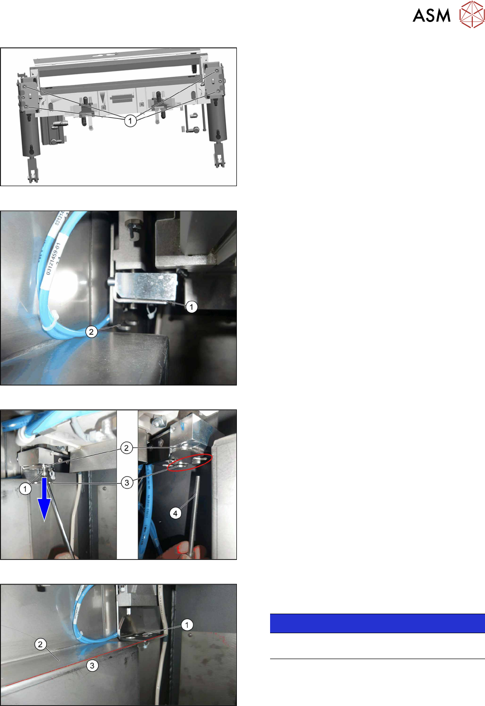
Fig.346: Cutter fastening screws
► Remove the four fastening screws(1) on the cut-
ter mount.
Fig.347: Cutter on lifting aid
► The cutter mount(1) will move downwards to the
support plate(2).
Fig.348: Moving the cutter down
► Loosen the screw on the cutter lifting aid(1).
► Move the entire lifting aid downwards(2) until it
touches the end position(3).
► Remove the long screw(4).
Fig.349: Lifting aid and support edge
The cutter lifting aid(1) is level(3) with the support
edge of the sliding plate(2).
NOTICE!
For better view the picture is without cutter. The
cutter will be removed in the following step.
.
11 Cutter
11.3 Replacing the Cutter on the COT Insert [03066690-xx]
254 Service Manual SIPLACE TX Series 06/2017
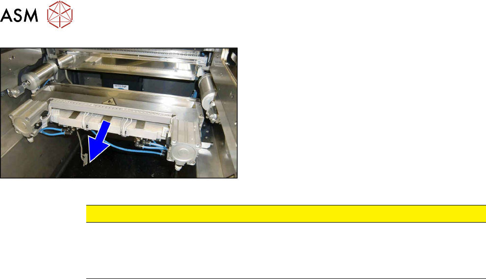
Fig.350: Pulling out the cutter
► Slide out the cutter unit on the support edge of
the machine.
CAUTION
Additional work
► For all further work, either fix the cutter to the mounting plate with four hexagon
socket-head screws M6 or use screw clamps to fasten the cutter to a sturdy table.
► Do not place the cutter onto the pneumatic connections (down on the lifting cylinders).
Installation
► Installation is performed by following the above instructions in reverse order.