00198150-02_SM_TX_en.pdf - 第233页
10 COT Insert 10.1 COT Insert - Overview Service Manual SIPLACE TX Series 06/2017 233 10 COT Insert DANGER Observe User Manual ► Please observe the safety instructions in the user manual for all work! 10.1 COT Insert - O…

9 Nozzle Changers and Nozzle Stations
9.4 Replacing the Control Board Cable NC Valve [00334212-xx]
232 Service Manual SIPLACE TX Series 06/2017
10 COT Insert
10.1 COT Insert - Overview
Service Manual SIPLACE TX Series 06/2017 233
10 COT Insert
DANGER
Observe User Manual
► Please observe the safety instructions in the user manual for all work!
10.1 COT Insert - Overview
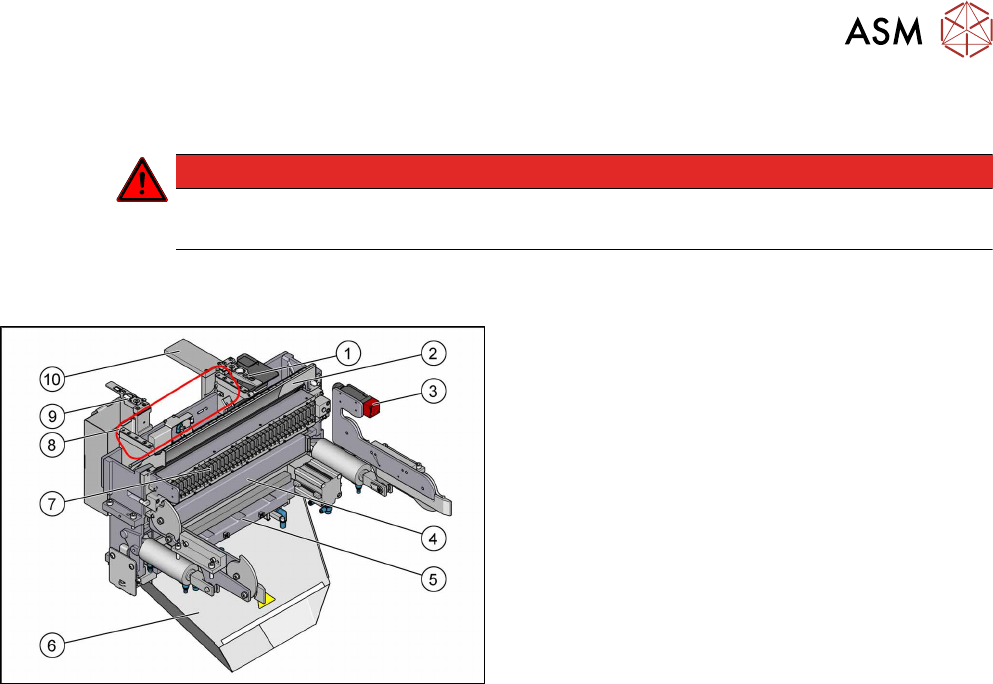
Fig.311: COT insert overview
1. Nozzle station (standard)
2. Empty tape duct
10.6 "Replacing the Empty Tape Duct Assembly
[03052576-xx]" [}244]
3. Safety switch for the component trolley
4. Feeder unlocking device
10.4 "Replacing the 40-Fold Feeder Unlocking
Device [03011582-xx]" [}239]
5. Cutter
6. Waste tape chute
7. Feeder control unit (FCU)
10.5 "Replacing the Feeder Control Unit
(FCU)" [}241]
8. Assembly positions for the nozzle changers
9. Reject bin with nozzle station (optional)
10. Component deposit – reject plate (option)
10.7 "Replacing Component Deposit
[03117664-xx]" [}247]
10 COT Insert
10.2 Installation Positions of COT Insert (Table Positions)
234 Service Manual SIPLACE TX Series 06/2017
10.2 Installation Positions of COT Insert (Table Positions)
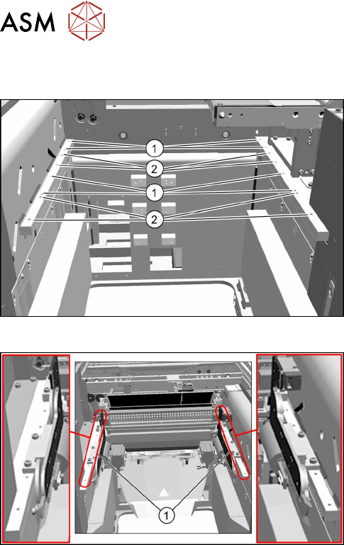
Fig.312: Installation positions
The inner and outer mounting positions depend on the
machine type.
The following installation positions apply to the
SIPLACE TX-Series:
1. COT insert at inner position:
SIPLACE TX1, TX2: location 2
SIPLACE TX2i: location 1 and 2
2. COT insert at outer position:
SIPLACE TX1, TX2: location 1
Fig.313: Example: inner position
Example:
1. COTi central unit mounted at inner position