00198150-02_SM_TX_en.pdf - 第118页
6 Gantries 6.4 MHCU, Boards and Camera 118 Service Manual SIPLACE TX Series 06/2017 Installation ► Follow the removal instructions in reverse order for installation. Also observe the following in- structions: CAUTION Ins…
6 Gantries
6.4 MHCU, Boards and Camera
Service Manual SIPLACE TX Series 06/2017 117
6.4.3 Replacing the Vision Head Interface (VHI) [03115454-xx]
Parts, equipment and tools
●
Vision Head Interface (VHI) [03115454-xx]
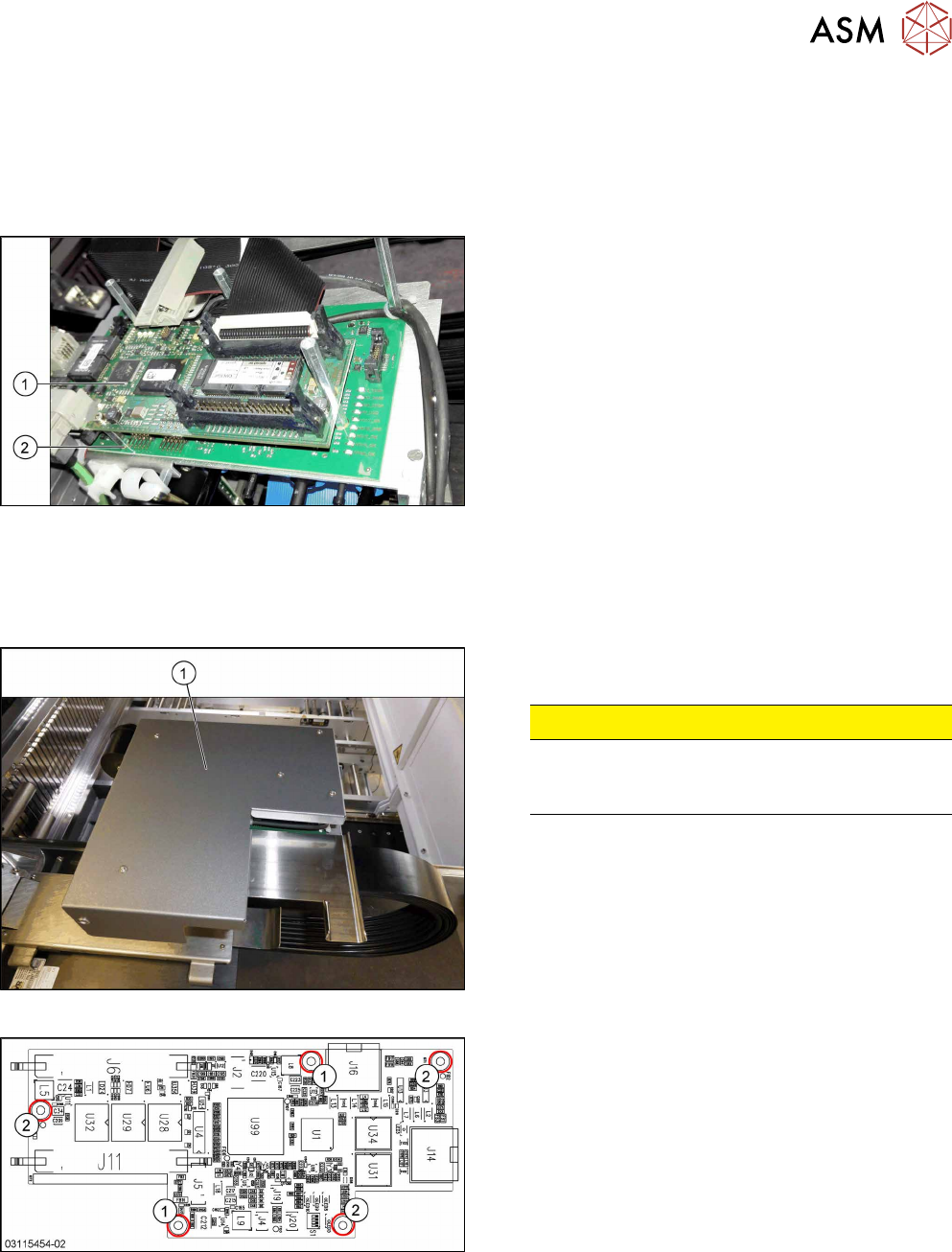
Overview
Fig.147: Boards on the gantry
1. Vision Head Interface (VHI)
2. Head interface
Removal
► Switch off the machine, disconnect it from the power supply and secure it to prevent
unauthorized reactivation. Observe the instructions in section 1.2 "Preparatory Work..." [}15].
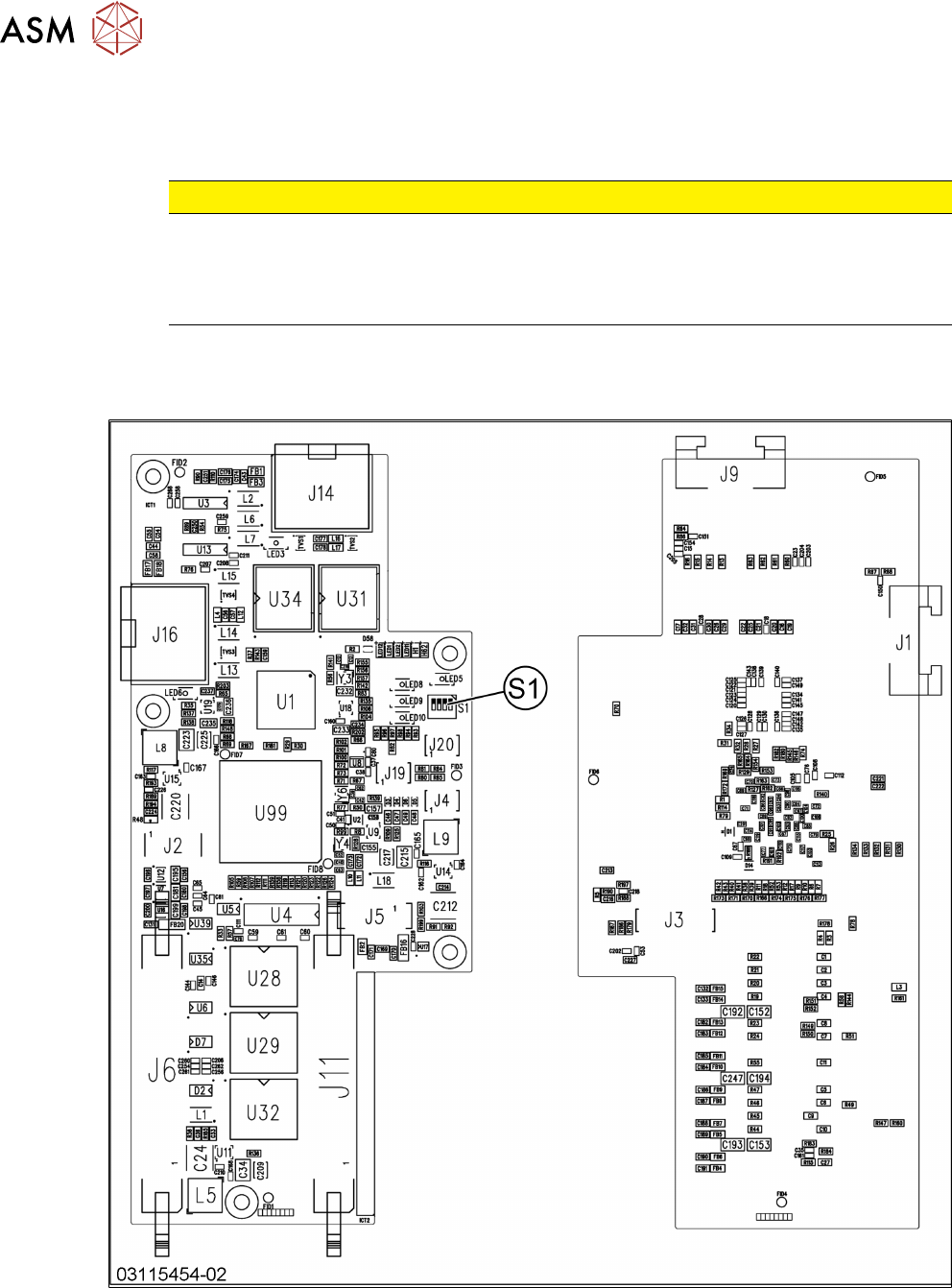
Fig.148: Board cover
► Remove the five fastening screws and lift the
board cover(1) off.
CAUTION!
Switch off the machine
To avoid short circuits, only dismantle the cover
when the machine is switched off!
.
Fig.149: Vision head interface
1. Screws M3x6 [03007733‑xx]
2. Spacer bolts M3x30 [00315647‑xx] (for cover)
► Unplug all electrical connections to the VHI. You
may want to mark the positions of these connec-
tions to make clear assignment easier later on.
► Remove the five screws and spacer bolts fasten-
ing the VHI and remove the board.
6 Gantries
6.4 MHCU, Boards and Camera
118 Service Manual SIPLACE TX Series 06/2017
Installation
► Follow the removal instructions in reverse order for installation. Also observe the following in-
structions:
CAUTION
Installation instructions
► Set the DIP switch S1 on the board (see below).
► Perform a embedded software download (see 6.4.11 "eSW Download (SW
70x)" [}130]).
See also
2 Vision Head Interface [03115454-xx] [}118]
2 Vision Head Interface [03115454-xx] [}118]
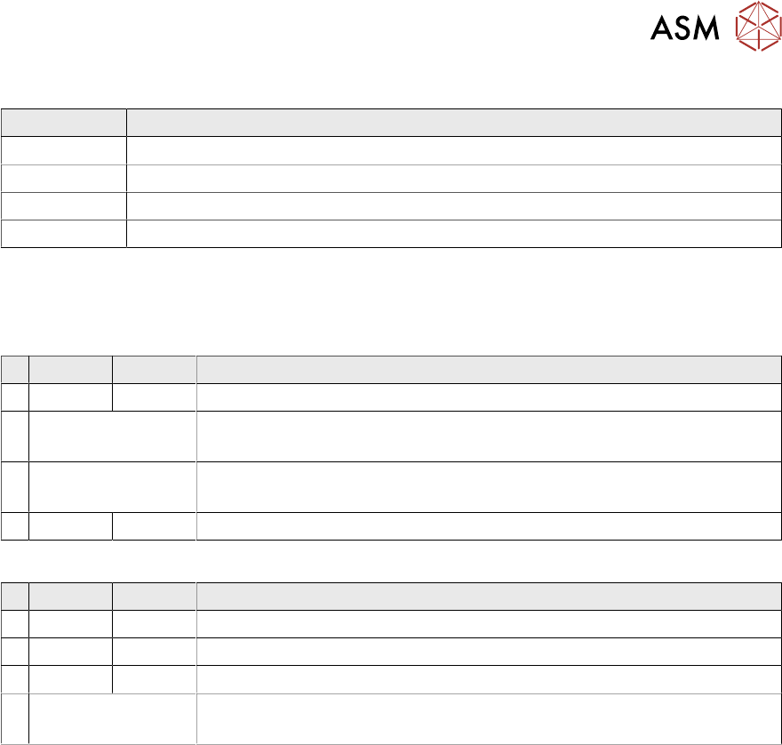
6.4.3.1 Vision Head Interface [03115454-xx]
Fig.150: Vision head interface
6 Gantries
6.4 MHCU, Boards and Camera
Service Manual SIPLACE TX Series 06/2017 119
Connectors
Connector Description
J14 CAM1 – PCB camera
J16 CAM2 – component camera
J6, J11 Trailing cable
J5 Power supply
Switch S1
The S1 settings depend on the board version:
Switch S1 [03115454-01]
ON OFF Note
4 OFF CAN-R ON/OFF
3 See text X-Series S: OFF
All other machines: ON
2 See text X-Series S: ON
All other machines: OFF
1 ON Spread OFF/ON
Switch S1 [03115454-02 and -03]
ON OFF Note
4 OFF CAN-R ON/OFF
3 ON EEPROM
2 OFF Reserve
1 See text X-Series S: OFF
All other machines: ON