00198150-02_SM_TX_en.pdf - 第239页
10 COT Insert 10.4 Replacing the 40-Fold Feeder Unlocking Device [03011582-xx] Service Manual SIPLACE TX Series 06/2017 239 Installing the lifting mechanics Fig.324: Installing the lifting mechanics ► Mount the interloc…
10 COT Insert
10.3 Replacing the COTi Central Unit and Lifting Mechanics
238 Service Manual SIPLACE TX Series 06/2017
Installation of central unit
Follow the removal instructions in reverse order for installation.
► If necessary move the cutter and the FCU from the old to the new COTi.
Replacing the Feeder Control Unit (FCU) [}241]
Replacing the Cutter on the COT Insert [03066690-xx] [}252]
► Lift the COTi into the machine. Use a suitable lifting device.
► Reconnect all cables and hoses. If required, use the detailed circuit diagrams folder.
► Move the COTi into its final position on the machine frame.
Take care not to damage the cables and hoses.
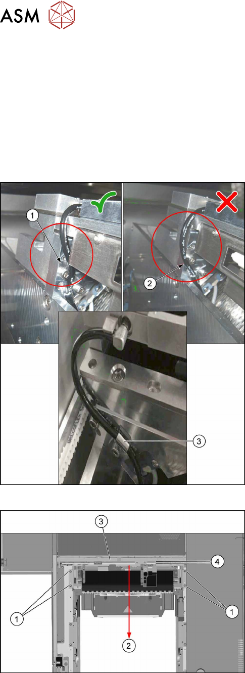
Fig.322: Tubing of the nozzle station air supply
► Check the tubing of the nozzle station air supply:
1. Tubing 1 is recommended. The tube is running
behind the screw head, so the lining of the tube
will not touch the conveyor belt.
2. Tubing 2 is not recommended, as it may touch
the conveyor belt and will be cut over time.
3. Use the hose clamp.
Fig.323: Fixing the central unit (shown from above)
► Put in the four screws(1) in position and loosely
tighten them.
► Move the central unit to the outer side of the
machine(2) to ensure a maximum distance(4) to
the conveyor side(3).
► The further installation of the central unit is performed by following the above instructions in
the reverse order.
10 COT Insert
10.4 Replacing the 40-Fold Feeder Unlocking Device [03011582-xx]
Service Manual SIPLACE TX Series 06/2017 239
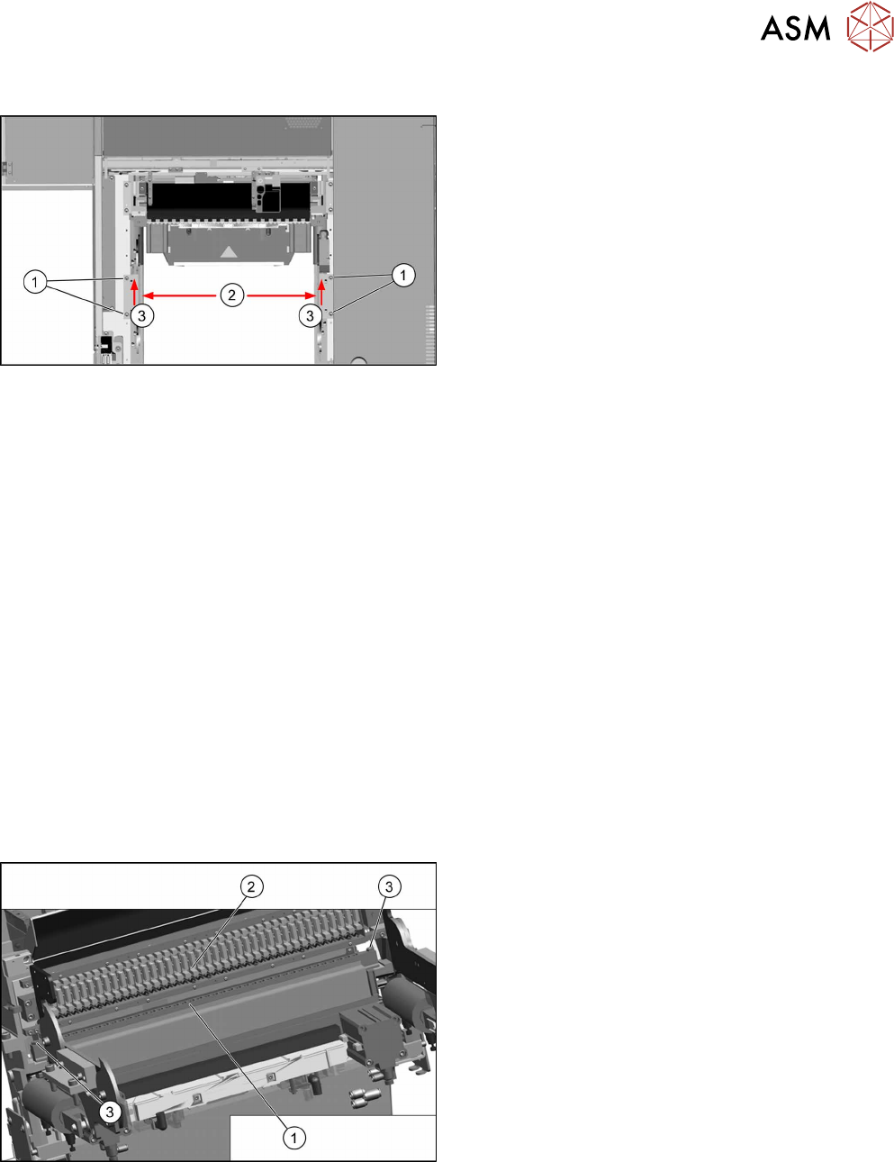
Installing the lifting mechanics
Fig.324: Installing the lifting mechanics
► Mount the interlock safety switch to the right lift-
ing mechanics.
► Place both lifting mechanics (left and right) in
position and fix them with two screws(1) each.
► Move both lifting mechanics to the outer posi-
tion(2) push them towards the inner side(3) and
tighten the screws(1).
► Reconnect the lifting mechanics to the pneumatic cylinders.
► Insert the locking flap bolt and place the washers in the correct position! Start at the inner side
at the COTi.
► Close the locking flap to fix the connection between the lifting mechanics and pneumatic cylin-
der.
► Perform necessary calibrations for the location.
See also
2 Replacing the Feeder Control Unit (FCU) [}241]
2 Replacing the Cutter on the COT Insert [03066690-xx] [}252]
10.4 Replacing the 40-Fold Feeder Unlocking Device
[03011582-xx]
Parts, equipment and tools
●
Feeder unlocking device 40-fold [03011582-xx]
Overview
Fig.325: Feeder unlocking device on COTi
1. Feeder unlocking device (under the FCU)
2. Feeder control unit (FCU)
3. Fastening screws (SW10)
The feeder unlocking device is installed at the loca-
tions in the COTi.
10 COT Insert
10.4 Replacing the 40-Fold Feeder Unlocking Device [03011582-xx]
240 Service Manual SIPLACE TX Series 06/2017
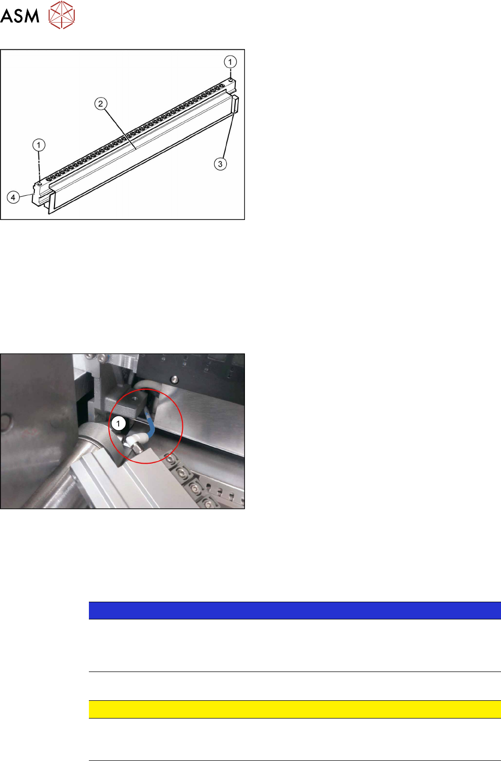
Fig.326: Feeder unlocking device
1. Two fastening screws
2. Complete feeder unlocking device
3. Connector for flat ribbon cable
4. Pneumatic connection
Removal
► Switch off the machine, disconnect it from the power supply and secure it to prevent
unauthorized reactivation. Observe the instructions in section 1.2 "Preparatory Work..." [}15].
► Unplug the flat ribbon cable from the connector.
► Remove the two fastening screws.
► Pull the flat ribbon cable out of the side of the connector. You may have to lift the feeder un-
locking device slightly to do this.
Fig.327: Pneumatic connection
► Lift the feeder unlocking device up and off and
pull the pneumatic connection(1)off.
Installation
Follow the removal instructions in reverse order for installation. Also observe the following instruc-
tions:
► Reconnect the system to the electrical and compressed air systems.
NOTICE
Pneumatic connection
You might find it advisable to remove the cover on the back of the COTi. This gives the
compressed air hose more room to be moved. In certain circumstances, the COT insert
may need to be loosened and pulled out slightly to the front.
► Carefully press the feeder unlocking device towards the back and insert the fastening screws.
CAUTION
Do not pinch the cable.
► Make sure not to pinch or damage the cables running at the back (connected to the
FCU).