00198150-02_SM_TX_en.pdf - 第169页
7 Conveyor 7.6 Fiber Optic Cable and Light Barriers Service Manual SIPLACE TX Series 06/2017 169 Overview Fig.231: Laser light barrier 1. Fastening screw 2. Setting screws Procedure with setting gauge Fig.232: Focusing…
7 Conveyor
7.6 Fiber Optic Cable and Light Barriers
168 Service Manual SIPLACE TX Series 06/2017
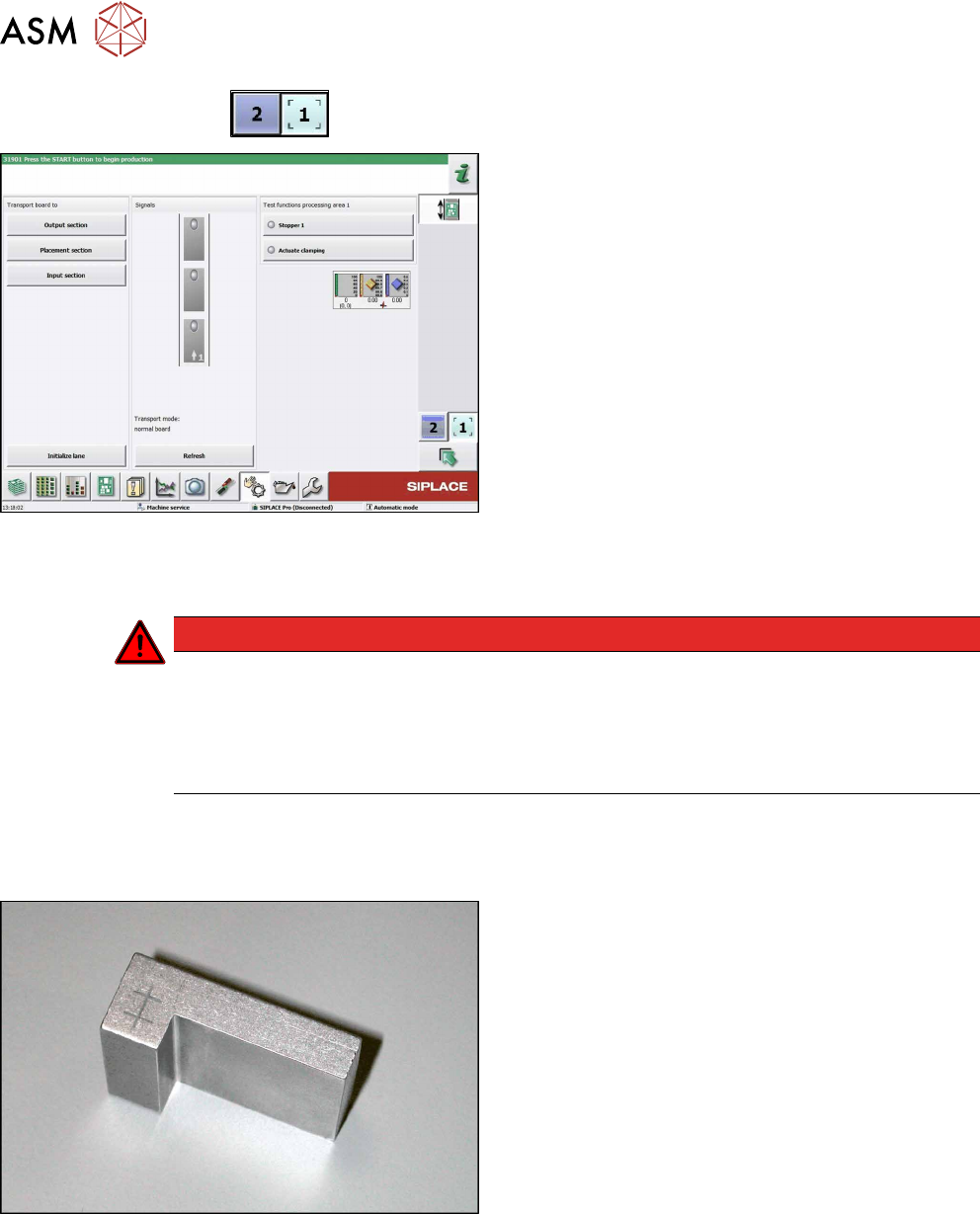
► Use the
button to select the required conveyor lane.
Fig.229: Checking function of the laser light
► Check the function of the laser light barrier. To do
this, move a board through the conveyor.
► Correct the laser light barrier setting, if necessary
(see Correcting the Laser Light Barrier Setting).
7.6.3 Correcting the Laser Light Barrier Setting
DANGER
Laser class 2
The laser light barrier transmitter emits class 2 laser beams. You therefore do not require
additional protective measures!
► However, you should never look into the laser beam.
► Adjust the laser beam only from the rear side of the laser!
Parts, equipment and tools
●
Recommendation for new version of receiver (silver receiver surface):
Semi-transparent paper or plastic (for better recognition of laser beam)
Fig.230: Setting gauge
Optional:
●
Setting gauge for conveyor laser light barrier
[00369205-xx]
7 Conveyor
7.6 Fiber Optic Cable and Light Barriers
Service Manual SIPLACE TX Series 06/2017 169
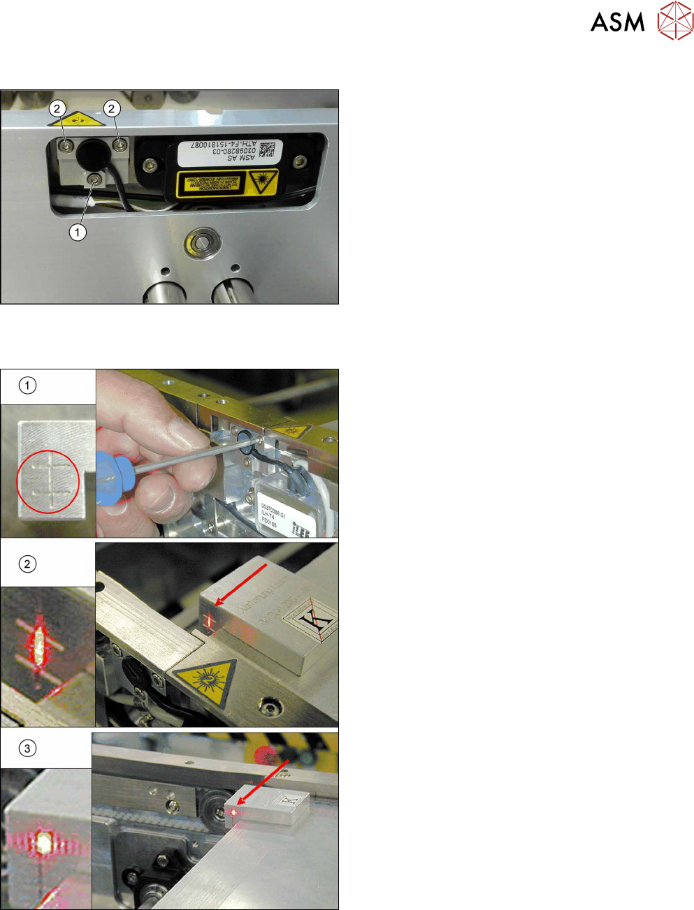
Overview
Fig.231: Laser light barrier
1. Fastening screw
2. Setting screws
Procedure with setting gauge
Fig.232: Focusing the laser beam (using example of X-Series)
1. Setting the laser light barrier
2. Minimum width
3. Maximum width
► Set the maximum conveyor width.
► Select Enable safety mode in software.
► Activate the relevant laser diode using the input/
output functions in the station software.
► Check the path of the laser beam with the help of
the gauge.
► With the help of the three setting screws, adjust
the laser beam to the center of the gauge cross
(1).
► Now position the conveyor to minimum width(2)
and check the setting.
► Check the PCB reference corner and reteach, if
necessary.
7 Conveyor
7.6 Fiber Optic Cable and Light Barriers
170 Service Manual SIPLACE TX Series 06/2017
Procedure without setting gauge
► Set the maximum conveyor width.
NOTICE
Deviation of the laser beam has the greatest effect at maximum conveyor width
► Select "Enable safety mode".
► Activate the relevant laser diode using the input/output functions in the station software.
► Use the top two screws to set the laser beam so that it is correctly aligned with the laser recei-
ver.
CAUTION
Screws on the laser transmitter
► Hand-tighten the lower screw. The top two screws are used to set the laser beam.
These may not be fully tightened, otherwise the laser transmitter could be damaged.
NOTICE
Semi-transparent paper or plastic
► Use semi-transparent paper or plastic to make the laser beam visible on the receiver.
► Now position the conveyor to minimum width and check the setting.
► Check the PCB reference corner and reteach, if necessary.
7.6.4 Repairing the Fiber Optic Cable
To avoid machine downtimes, it is possible to repair fiber optic cables temporarily, using the repair
hose.
NOTICE
Repair hose for fiber optic cable LL3-TV05
► The repair hose may only be used for short periods to avoid machine downtimes.
► The repair hose may only be used once per fiber optic cable.
► The fiber optic cable must be replaced during the next repair or maintenance cycle.
NOTICE
No guarantee
► No guarantee is given if the fiber optic cable is repaired using the repair hose.
► There is no long-term experience with the repair hose.
► Depending on the board width, the intensity of the light beam may diminish in such a
way that an evaluation is no longer possible.
► The repair hose must not be bended. For this reason, there is an additional danger of
rupture after the repair, in areas where the fiber optic cable is routed in narrow radii.
If there is another rupture of the fiber optic cable and no complete replacement is possible, proceed
as follows:
► Replace the defective part of the fiber optic cable in such a way that only one repair hose is
used.