00198150-02_SM_TX_en.pdf - 第143页
7 Conveyor 7.2 Lifting Table Service Manual SIPLACE TX Series 06/2017 143 7.2.4 Setting the Parallelism and Height of the Lifting Table Plate DANGER Press the EMERGENCY STOP! Before performing adjustment work you must en…

7 Conveyor
7.2 Lifting Table
142 Service Manual SIPLACE TX Series 06/2017
CAUTION
Installation instructions
► The motor crank and the brackets need to be removed and refitted on the new lifting
table motor.
Use the old lifting table motor as a reference.
Observe the position and number of washers used.
► Tighten the clamping screw on the motor crank.
► Make sure that the motor connection cables do not rub against any parts.
► Place the lifting table plate onto the guidance pins. Make sure that the fastening
screws slide properly into the precut thread.
► Check the parallelism of the lifting table plate (see 7.2.4 "Setting the Parallelism and
Height of the Lifting Table Plate" [}143]).
► Check the free movement of the lifting table (see 7.2.5 "Checking Free Movement of
Lifting Table" [}144]).
► Set the lifting table height (see 7.2.4 "Setting the Parallelism and Height of the Lifting
Table Plate" [}143]).
► Calibrate the lifting table motor and then perform a reference run (see Calibrating the
Conveyor Functions).
► For more information about the conveyor control refer to section 7.7.1.1 "Conveyor
Control TSP420 [03087642-xx]" [}182].
See also
2 Replacing the COTi Central Unit and Lifting Mechanics [}235]
7 Conveyor
7.2 Lifting Table
Service Manual SIPLACE TX Series 06/2017 143
7.2.4 Setting the Parallelism and Height of the Lifting Table Plate
DANGER
Press the EMERGENCY STOP!
Before performing adjustment work you must ensure that the lifting table has been secured
against movement!
Overview
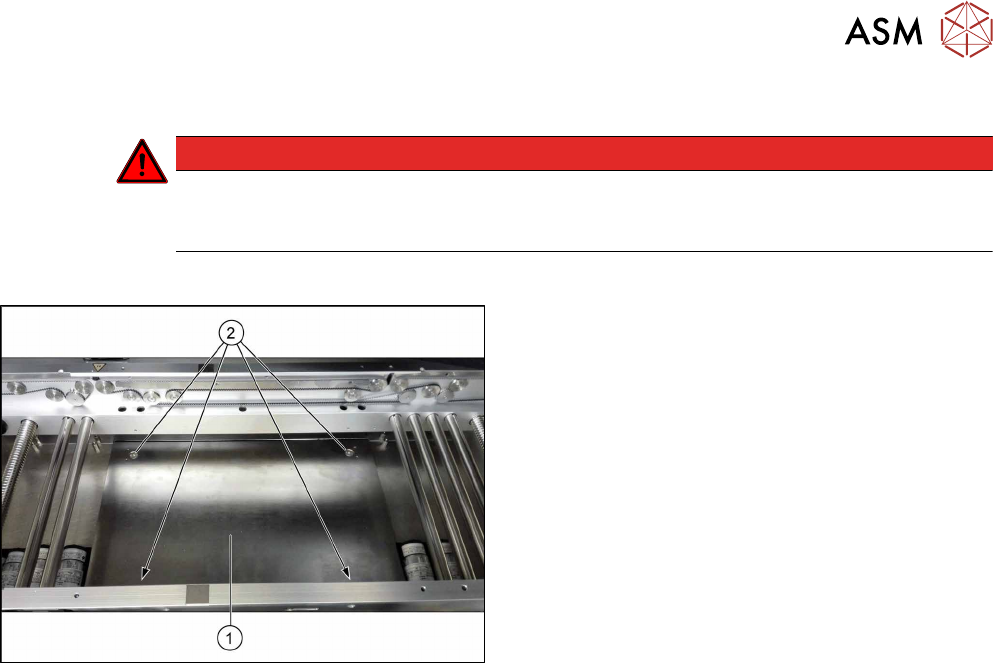
Fig.190: Lifting table plate
1. Lifting table plate
2. Fastening screws for lifting table plate
Setting
► Use the software to move the conveyor rails to maximum width.
► Remove the screws fastening the lifting table plate (countersunk screws) but do not remove
the lifting table plate.
► Use the software to clamp the lifting table (without board).
► Underneath the fastening screws, there are setting screws (socket-head5).
Use these setting screws to set the lifting table plate so that it has no play between it and the
clamping edge.
► Check all four corners of the lifting table for any play.
► Check the setting by clamping a board into place. Check all corners to see whether there is
any play.
► Insert and tighten the four screws fastening the lifting table plate.
► Calibrate the zero position of the lifting table motor.
7 Conveyor
7.2 Lifting Table
144 Service Manual SIPLACE TX Series 06/2017
7.2.5 Checking Free Movement of Lifting Table
After all work on the lifting table mechanics check the free movement of the lifting table.
Fig.191: Select operator level
► Click the
button to enter the Settings
menu.
► Click the
button to open the Check and set
user settings menu.
► Switch to operator level Machine service or bet-
ter.
Fig.192: Maintenance menu
► Click the
button to enter the maintenance
menu.
► Click the
button.
► Click the Conveyor motor verification button.
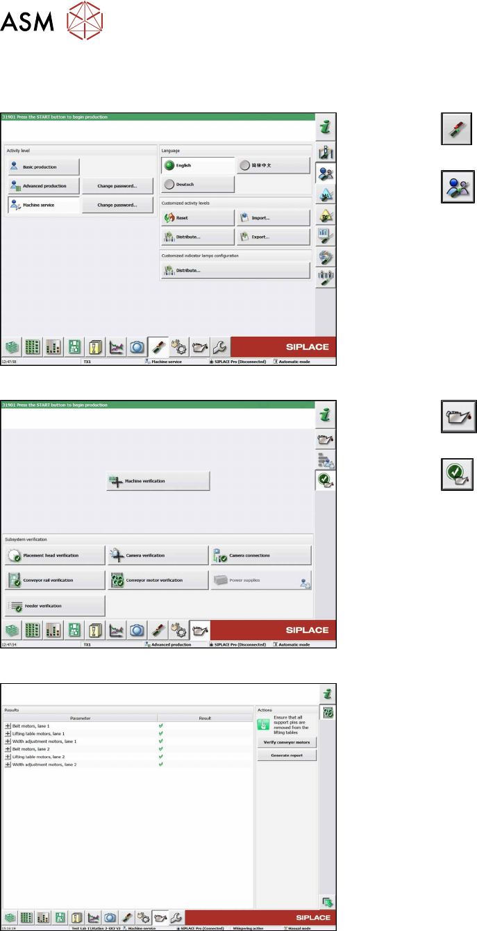
Fig.193: Verify conveyor motors
► Click the Verify conveyor motors button to run
check.
► Click the Generate report button to view details.
See also
2 Replacing the Lifting Table Plate [03114873-xx] [}136]