00198150-02_SM_TX_en.pdf - 第114页
6 Gantries 6.4 MHCU, Boards and Camera 114 Service Manual SIPLACE TX Series 06/2017 Fig.142: Head adapter MHCU (example of C&P20P shown) ► Unplug all electrical connections to the head ad- apter (1) . You may want…
6 Gantries
6.4 MHCU, Boards and Camera
Service Manual SIPLACE TX Series 06/2017 113
6.4 MHCU, Boards and Camera
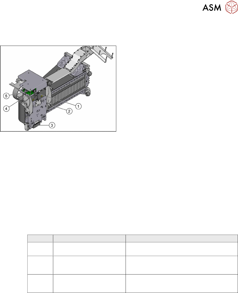
6.4.1 Gantries - MHCU, Boards and Camera - Overview
Fig.141: MHCU, boards and camera
1. Head adapter
6.4.2 "Replacing the Head Adapter for the
MHCU" [}113]
2. Gantry temperature sensor
6.4.6 "Replacing the Gantry Temperature
Sensor" [}125]
3. PCB camera
Replacing the PCB Camera
4. Head interface
6.4.4 "Replacing the Head Interface" [}120]
5. Vision Head Interface (VHI)
●
6.4.8 "Error "Gantry Crash"" [}128]
●
6.4.9 "Anticrash Function" [}129]
●
6.4.10 "Count Error" [}129]
●
6.4.11 "eSW Download (SW 70x)" [}130]
See also
2 Replacing the Vision Head Interface (VHI) [03115454-xx] [}117]
6.4.2 Replacing the Head Adapter for the MHCU
Parts, equipment and tools
The following spare parts can be replaced:
●
MHCU assembly, compatible [03090990Sxx]
●
MHCU assembly [03109668‑xx]
●
PCB / X base adapter C&P [03045647Sxx] from FS08
●
Module / X base adapter TWIN [03062201Sxx]
Head Adapter Number of MHCU, base adapters
CPP Module X base adapter C&P
[03071420-xx]
1x MHCU [03090990Sxx] from FS04
1x PCB / X base adapter C&P [03045647Sxx]
C&P20P Module X base adapter C&P 20
P
[03109399-xx]
1x MHCU [03090990Sxx] from FS04
1x PCB / X base adapter C&P [03045647Sxx]
Twin Head adapter Twin (M)HCU /
SX4
[03082096-xx]
2x MHCU [03090990Sxx] from FS04
1x module/ X base adapter TWIN [03062201Sxx]
Removal
► Switch off the machine, disconnect it from the power supply and secure it to prevent
unauthorized reactivation. Observe the instructions in section 1.2 "Preparatory Work..." [}15].
► You may need to dismantle the placement head for better access.
Replacing the SIPLACE CPP/M Head [}206]
Replacing the SIPLACE TwinHead [}210]
Replacing the SIPLACE C&P20 P/M2 Head [}202]
6 Gantries
6.4 MHCU, Boards and Camera
114 Service Manual SIPLACE TX Series 06/2017
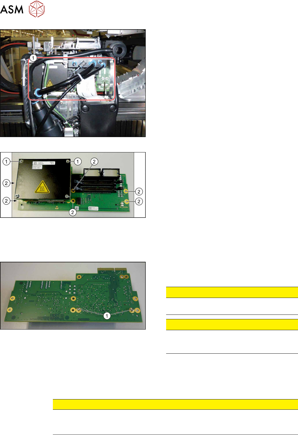
Fig.142: Head adapter MHCU (example of C&P20P shown)
► Unplug all electrical connections to the head ad-
apter(1). You may want to mark the position to
make clear assignment easier later on.
Fig.143: Head adapter
► Remove the screws(2) fastening the head ad-
apter.
► In addition, the head adapter is fastened with the
topmost two MHCU screws(1)in each case. Re-
move these two screws as well.
► Carefully pull the head adapter down and off.
The head adapter is connected to the head inter-
face from below via a press-fit connection.
Converting the MHCU
If you have ordered the base adapter without MHCU(s) you will have to convert the MHCU(s). Pro-
ceed as follows:
Fig.144: Head adapter backside
► Remove the two screws(1) fastening the MHCU
on the back of the board and carefully pull the
MHCU off the base adapter.
CAUTION!
Washers
Make sure that you do not lose the washers.
.
CAUTION!
Pins
Make sure that you do not damage the pins un-
der the MHCU.
.
► Only for Twin head: Repeat the procedure for the second MHCU.
Installation
► Follow the removal instructions in reverse order for installation. Also observe the following in-
structions:
CAUTION
Installation instructions
► Check the embedded software and perform a download if needed (see 6.4.11 "eSW
Download (SW 70x)" [}130]).
See also
2 Replacing the SIPLACE CPP/M Head [}206]
2 Replacing the SIPLACE TwinHead [}210]
2 Replacing the SIPLACE C&P20 P/M2 Head [}202]
6 Gantries
6.4 MHCU, Boards and Camera
Service Manual SIPLACE TX Series 06/2017 115
6.4.2.1 X Base Adapter C&P [03045647-xx]
This board is used for C&P20x and CPP heads on SIPLACE X-Series S, SX4/DX4 and TX-Series
machines.
NOTICE
C&P20P
The X base adapter needs at least function level 08 for the C&P20 P head. In this case,
you may need longer flat ribbon cables.
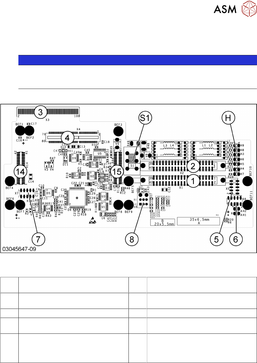
Version 09
Fig.145: X base adapter C&P
Connections [03045647-09]
1, 2 X1-X2 flat ribbon connection for CPP or
C&P20
3 X3 Connection to the head interface
board C700
4, 14,
15
X4, X14, X15 – connector for (M)HCU 5 X5 Test connector for FPGA
6 X6 Programming connector for FPGA 7 X7 Test connector (M)HCU
8 X8 connectors for inlet vacuum sensor
(cable X1a)
H LED H3- H9
S1 Switch S1 intermediate circuit voltage
Z axis
40V C&P20 (switch top)
150V CPP(switch bottom)