00198150-02_SM_TX_en.pdf - 第221页
8 Placement Heads and Stationary Cameras 8.6 Stationary Camera Service Manual SIPLACE TX Series 06/2017 221 8.6.4 PCBs Stationary Cameras 8.6.4.1 Vision LED Controller VLC25/33 GigE DTC [03117981‑xx] [03117587‑xx] The Vi…

8 Placement Heads and Stationary Cameras
8.6 Stationary Camera
220 Service Manual SIPLACE TX Series 06/2017
8.6.3 Troubleshooting Stationary Cameras
Error / problem
●
Errors arise during nozzle scanning, even though the nozzle has already been checked to en-
sure that it is clean.
●
During camera verification (FCCS), it is difficult to achieve the necessary illumination.
●
Increased component rejection rate, particularly with low-contrast components.
Cause of hazard
If one or more of these errors occurs, the cause may be a dirty camera.
Solution
► Clean the stationary cameras. Please read the technical information [DE: TI2014-10D09] [EN:
TI2014-10E09] for more information.
Problem
●
Error message 37752: "The LED test of the camera illumination failed" at GigE cameras
Solution
► Please contact the SIPLACE service team for more information.
Give them the following reference number: TI2015-08V03.
8 Placement Heads and Stationary Cameras
8.6 Stationary Camera
Service Manual SIPLACE TX Series 06/2017 221
8.6.4 PCBs Stationary Cameras
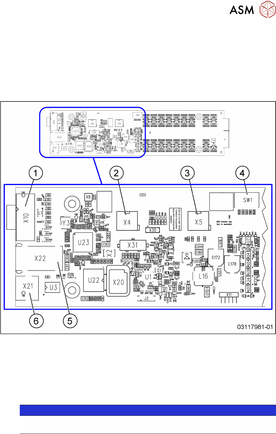
8.6.4.1 Vision LED Controller VLC25/33 GigE DTC [03117981‑xx] [03117587‑xx]
The
Vision LED Controller VLC33 GigE DTC [03117981-xx] and
Vision LED Controller VLC25 GigE DTC [03117587-xx]
boards are identical, except for the connectors X21 and X22. These connectors are only present on
the VLC25 board.
The boards are part of the stationary camera SST25/33 GigE.
Fig.301: Vision LED Controller VLC25 GigE DTC [03117587-xx]
1 CAN bus 2 X4: Cable for power supply
3 X5: Cable for power supply, bridge to
FC camera
(Not used in TX-Series)
4 DIP switch SW1 (see below)
5 Connector X22 (VLC25 only) 6 Connector X21 (VLC25 only)
NOTICE
X21 and X22
The connectors X21 and X22 are not used in TX-Series machines.

8 Placement Heads and Stationary Cameras
8.7 Calibration
222 Service Manual SIPLACE TX Series 06/2017
DIP switch S1 [03117587-xx] [03117981-01]
Switch Status Signal name Description
S1.1 OFF VCU_CODE OFF: normal operation, ON: Reset
Gantry 1 Gantry 2 Gantry 3 Gantry 4
S1.2 ON/OFF PORTAL_ID_0 OFF ON OFF ON
S1.3 ON/OFF GANTRY_ID_1 OFF OFF ON ON
S1.4 OFF SMD_LED OFF: standard LED, ON: SMD LED
S1.5 OFF CAN_H OFF: with CAN terminator
ON: without CAN terminator
S1.6 ON CAN_GROUP ON: IC camera , OFF: FC camera
8.7 Calibration
Overview
With the calibration of the component camera the following values are determined:
the relationship of "camera pixel size to resolution of machine measuring system (X,Y)", the "cam-
era center point in X and Y direction" and the "torsion angle of the CCD sensor in the camera". This
is following by determining the head offset and the segment offsets for the top and bottom.
●
Head offset: the head offset is the distance between the PCB camera and the nozzle (seg-
ment1). The target is a fixed value (X=0 and Y=‑105mm) to which an offset value (from the
head calibration) is added.
●
Segment offset top: the top segment offset involves turning the calibration tool in the compo-
nent camera in 0°, 90°, 180° and 270°. The value determined is that of the rotating center of
the nozzle tip in relation to the component camera center in the X and Y direction.
●
Segment offset bottom: the bottom segment offset involves recording and measuring the
calibration tool in the 0°, 90°, 180° and 270° positions. The value determined is that of the ro-
tating center point of the nozzle tip when the Z axis is extended in relation to the PCB camera.
Segment1 forms the reference (X=0,Y=0) to the other segments.