00198150-02_SM_TX_en.pdf - 第124页
6 Gantries 6.4 MHCU, Boards and Camera 124 Service Manual SIPLACE TX Series 06/2017 6.4.5 Replacing the PCB Camera Parts, equipment and tools ● PCB camera (type 34) 28 GigE [03101402‑xx] ● Loctite 241 [02101037‑xx] Overv…
6 Gantries
6.4 MHCU, Boards and Camera
Service Manual SIPLACE TX Series 06/2017 123
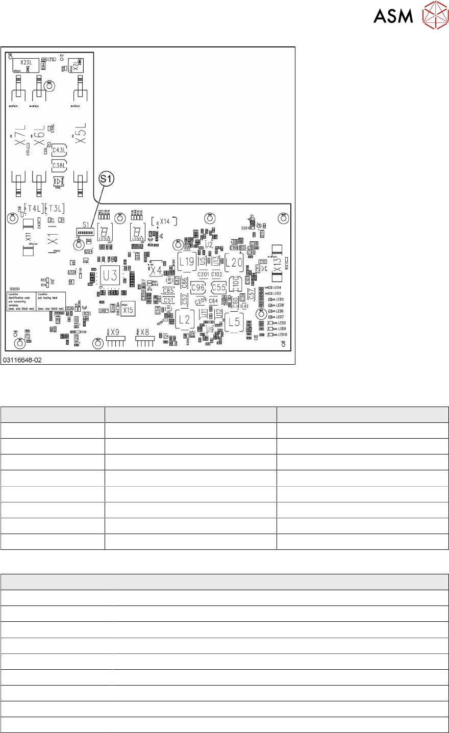
Fig.157: Head interface 2 TX
DIP switch S1 [03114439-02] [03116648-02]
DIP switches Gantry 1 Gantry 2
P0 OFF ON
P1 OFF OFF
BOOT OFF OFF
RES2 OFF OFF
RES1 OFF OFF
FAN OFF OFF
V-OFF OFF OFF
HCU_1 OFF OFF
LED [03114439-02] [03116648-02]
LED Description
X_TEMP X motor temperature
PF_BASE Power fail base
EM_STOP Emergency stop – safety circuit not closed
PF_LOC Power fail location
HCV1_ER MHCU1 error
HCV2_ERR MHCU2 error (only for Twin head)
HCV1_OK MHCU1 has booted and is ready
HCV2_OK MHCU2 has booted and OK
FPGA_OK FPGA booted and OK
The 7 segment display next to the DIP switch S1 provides information about MHCU1, the other 7
segment display is for MHCU 2 (if a Twin head is present).
6 Gantries
6.4 MHCU, Boards and Camera
124 Service Manual SIPLACE TX Series 06/2017
6.4.5 Replacing the PCB Camera
Parts, equipment and tools
●
PCB camera (type 34) 28 GigE [03101402‑xx]
●
Loctite 241 [02101037‑xx]
Overview
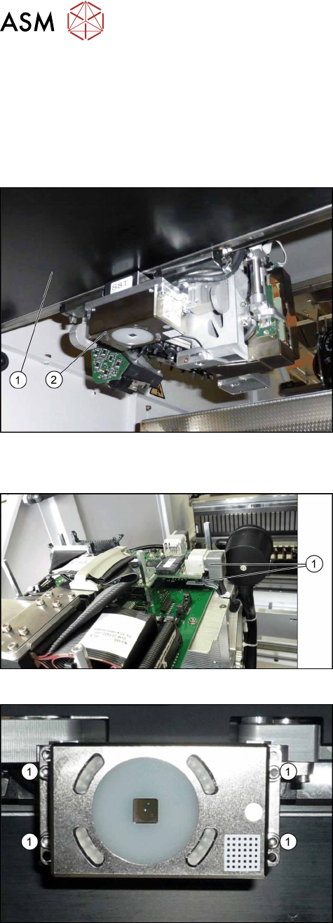
Fig.158: PCB camera on the gantry
1. Gantry
2. The PCB camera
The PCB camera is located on the underside of the
gantry, on the head mount.
Removal
Fig.159: Vision board
► Unplug the two connection cables X2 and X6(1)
from the VHI.
► Unthread the two cables as far as the PCB cam-
era.
Fig.160: PCB camera
► Remove the four screws (1) holding the PCB cam-
era. Mark their positions to make clear assignment
easier later on.
Installation
► Install the new PCB camera on the mount. Secure the screws with Loctite 241.
► Run the connection cable to the VHI and reconnect to the electrical system.
► After replacing the PCB camera, you will need to recalibrate the machine zero point and the
camera offset. Use the relevant software function in the Service menu.
6 Gantries
6.4 MHCU, Boards and Camera
Service Manual SIPLACE TX Series 06/2017 125
6.4.6 Replacing the Gantry Temperature Sensor
Parts, equipment and tools
●
MODUL / gantry sensor HCU [03112265‑xx]
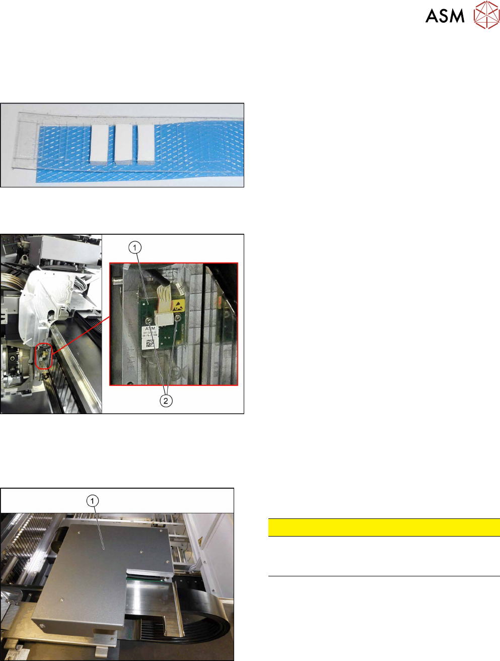
Fig.161: Gap filler
If required:
●
Silicon gap filler 7x7x16mm [03132222-xx]
Overview
Fig.162: Sensor on gantry
1. Gantry sensor HCU (temperature sensor)
2. Two fastening screws
Removal
► Switch off the machine, disconnect it from the power supply and secure it to prevent
unauthorized reactivation. Observe the instructions in section 1.2 "Preparatory Work..." [}15].
Fig.163: Board cover
► Remove the five fastening screws and lift the board
cover(1) off.
CAUTION!
Switch off the machine
To avoid short circuits, only dismantle the cover
when the machine is switched off!
.
► Remove the VHI (see 6.4.3 "Replacing the Vision Head Interface (VHI)
[03115454-xx]" [}117]).
► Unplug electric connection X4 on head interface (see also 6.4.4.1 "Head Interface
1/2" [}122]).
► Remove cable ties where necessary.