00198150-02_SM_TX_en.pdf - 第135页
7 Conveyor 7.1 Conveyor - Overview Service Manual SIPLACE TX Series 06/2017 135 7 Conveyor DANGER Observe User Manual ► Please observe the safety instructions in the user manual for all work! CAUTION Do not loosen or rem…
6 Gantries
6.6 Travel Ranges and Speed Monitoring
134 Service Manual SIPLACE TX Series 06/2017
6.6 Travel Ranges and Speed Monitoring
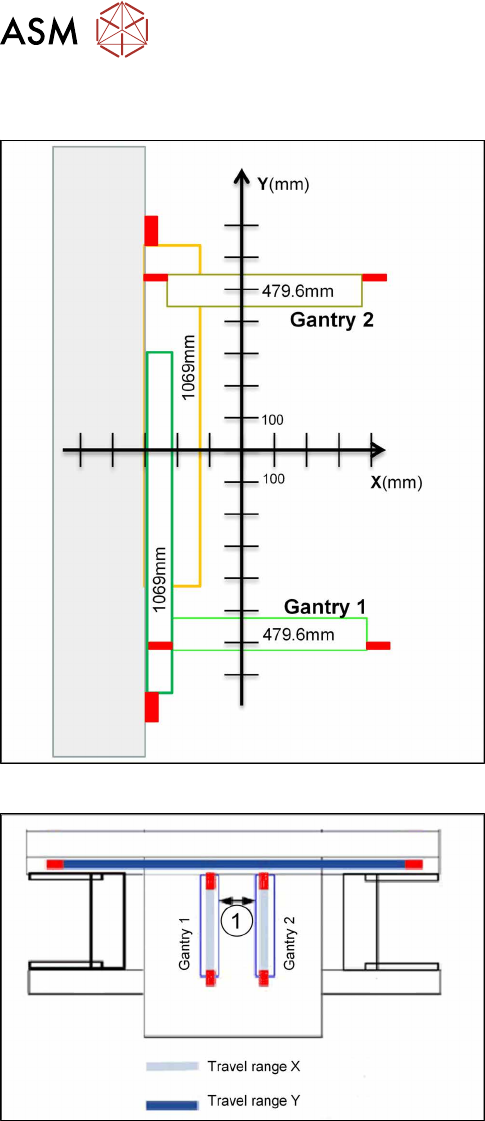
Fig.178: Travel ranges for X and Y axes
The travel range of the X and Y axes will be determ-
ined during machine calibration.
Travel range end of X axis
The end of the X axis travel range is + or - 0.2 mm be-
fore the software limit switch, which is 1.5 mm before
the buffer. A safety distance of 1.7 mm to the buffer is
adequate if the X axis moves into this area with ex-
cessive speed.
Travel range end of Y axis
The end of the Y axis travel range is + or - 2.0 mm be-
fore the software limit switch. The Y axis travel range
for a particular placement area is monitored in one dir-
ection by the software limit switch and a buffer. In the
other direction, there is a permanent exchange of
communication between the axes and their positions,
via the FDB bus.
Fig.179: Travel ranges for X and Y axes
1. Safety distance between the gantries during
placement: minimum 4mm.
Regardless of the placement mode (i-placement or al-
ternating), both gantries in one placement area only
move if they are referenced and if valid position in-
formation is available.
7 Conveyor
7.1 Conveyor - Overview
Service Manual SIPLACE TX Series 06/2017 135
7 Conveyor
DANGER
Observe User Manual
► Please observe the safety instructions in the user manual for all work!
CAUTION
Do not loosen or remove the wrong screws
The following applies to all work performed on the conveyor:
► Make sure that you do not loosen or remove any other screws except those ones ex-
plicitly mentioned. Loosening other screws could lead to irreparable misalignment or
damage to the conveyor.
CAUTION
Moving the conveyor side walls
► The fixed conveyor side wall is fastened by screws, the moveable conveyor side can
be moved by carefully pulling on the toothed belt of the width adjustment.
► After moving the conveyor side wall manually, you may need to teach the conveyor
side position during the conveyor reference run.
7.1 Conveyor - Overview
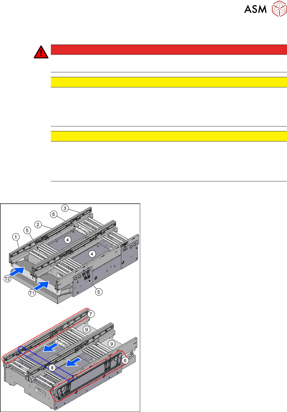
Fig.180: Conveyor overview
1. Input area
2. Placement area
3. Output area
4. Lifting tables
7.2 "Lifting Table" [}136]
5. Conveyor drives
7.3 "Conveyor Drive" [}146]
6. Width adjustment
7.4 "Width Adjustment" [}153]
7. Conveyor belts
7.5 "Conveyor Belt, Belt Drive and Hexagonal
Shaft" [}158]
8. Light barriers
7.6 "Fiber Optic Cable and Light Barriers" [}164]
9. TSP420
7.7 "Boards" [}181]
T1 = Conveyor lane 1
T2 = Conveyor lane 2
●
7.8 "Setting the Fixed Conveyor Rail" [}188]
The flexible dual conveyor has two conveyor lanes
that are electrically and mechanically independent of
one another.
By default, the fixed conveyor sides are in the "outer"
position.
Optionally, the fixed conveyor side can be selected -
right/right or left/left.
The PCB dual conveyor can also be operated as a
flexible single conveyor.
7 Conveyor
7.2 Lifting Table
136 Service Manual SIPLACE TX Series 06/2017
7.2 Lifting Table
7.2.1 Replacing the Lifting Table Plate [03114873-xx]
Parts, Equipment and Tools
●
Lifting table plate M-C [03114873-xx]
Overview
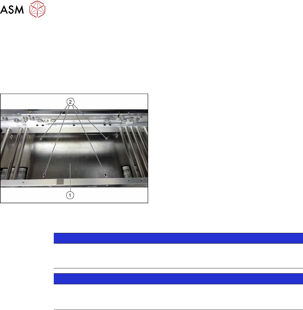
Fig.181: Lifting table plate
1. Lifting table plate
2. Fastening screws for lifting table plate
Removal
NOTICE
Does the lifting table stay in the top position?
If the lifting table remains in the top position and cannot be lowered, you will not be able to
dismantle the lifting table plate. In this case, call the SIPLACE Service team.
NOTICE
Lifting table plate guides
► Make sure that the lifting table guides are not mixed up. If you do, you will need to re-
set the parallelism of the lifting table plates.
► Use the software or manually move the conveyor rail into a position which allows you best ac-
cess.
– To move the conveyor rail manually, pull the toothed belt of the width adjustment unit.
► Switch off the machine, disconnect it from the power supply and secure it to prevent
unauthorized reactivation. Observe the instructions in section 1.2 "Preparatory Work..." [}15].
► Move all gantries out of the transport area as far as possible at one side of the machine.
► Remove the screws fastening the lifting table plate and remove the lifting table plate from the
machine. The lifting table plate is pinned to the lifting table plate guides but can be easily
pulled off them.