00198150-02_SM_TX_en.pdf - 第111页
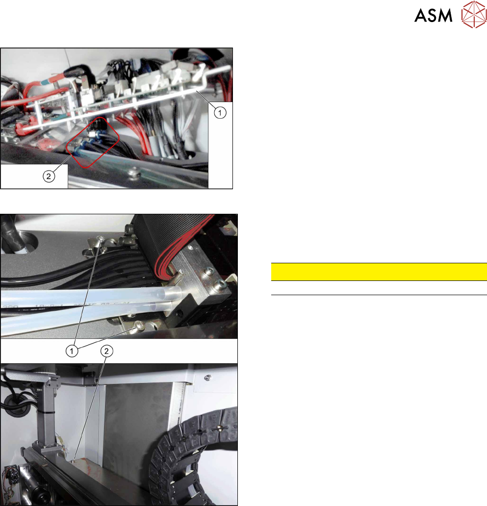
6 Gantries 6.3 Trailing Cable and Printed Circuit Boards Service Manual SIPLACE TX Series 06/2017 111 Fig.138: Hoses ► Lift up the console (1) to get access to the hoses (2) . ► Pull the hoses off. You may want to mar…
6 Gantries
6.3 Trailing Cable and Printed Circuit Boards
110 Service Manual SIPLACE TX Series 06/2017
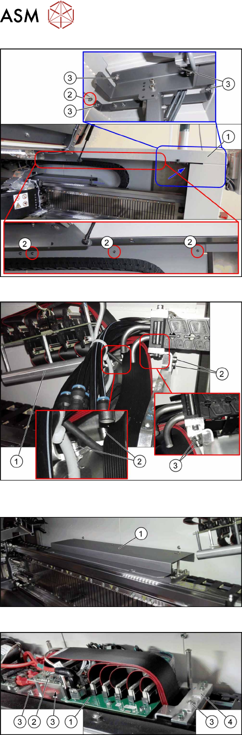
Fig.134: Removing the upper cover
► Remove the four nuts at(2) and the four nuts
at(3) on location1. Repeat for location2.
Ask for the help of a second person for the next step.
► Lift up the cover(1).
Fig.135: Trailing cable console
► Remove the four screws(2) fastening the trailing
cable console(1).
► Lift up the trailing cable console to have access
to the two screws (3) fastening the upper end of
the trailing cable.
► Remove the two screws(3).
Fig.136: Cover
► Remove the screws fastening the cover(1) on
the trailing cable interface and remove the cover.
Fig.137: Trailing cable interface and Vision base interface
► Mark the cables coming from the trailing cable on
the trailing cable interface(1) and Vision base in-
terface(2) to make clear assignment easier later
on.
► Unplug the cables coming from the trailing cable
at the trailing cable interface.
► Remove the three screws(3) fastening the con-
sole(4).
6 Gantries
6.3 Trailing Cable and Printed Circuit Boards
Service Manual SIPLACE TX Series 06/2017 111
Fig.138: Hoses
► Lift up the console(1) to get access to the
hoses(2).
► Pull the hoses off. You may want to mark their po-
sitions for easier replacement later on.
Fig.139: Trailing cable fastening screws
The trailing cable is fastened with three screws.
► Loosen the two screws(1).
► Loosen the screw(2).
CAUTION!
Do not open any other screws.
.
► Carefully remove the trailing cable from the machine.
6 Gantries
6.3 Trailing Cable and Printed Circuit Boards
112 Service Manual SIPLACE TX Series 06/2017
Installation
► Installation is performed by following the above instructions in the reverse order. Also observe
the following instructions:
CAUTION
Always handle the trailing cable with care
► If a vacuum pump is fitted, also observe the relevant assembly instructions
[00196845‑xx].
► Always handle the new trailing cable with care.
► You might need to enlist the help of a second person.
► Make sure that the flat ribbon cable and the pneumatic hoses are not rubbed against
any parts or folded. Look out for sharp edges.
► Prepare the trailing cable. Place the old and new trailing cables next to one another
and match the length of the new trailing cable hose to the old one.
► If you use the new holder, you will need to dismantle all attached items (boards etc.)
from the old holder and attach them to the new holder.
► If hose ends were damaged during removal, cut these with hose cutters.
► Clean the trailing cable contact surface on the machine base with a dry cloth.
► Carefully insert the new trailing cable into the prescribed position. Make sure you do
not fold or twist the trailing cable.
► Check that the power track chain runs parallel to the machine base. Move the gantry
back and forth.
► If it is difficult to push the hoses onto the tubes, moisten these first with white spirits or
isopropanol.
► Secure screws with Loctite 241 (see below).
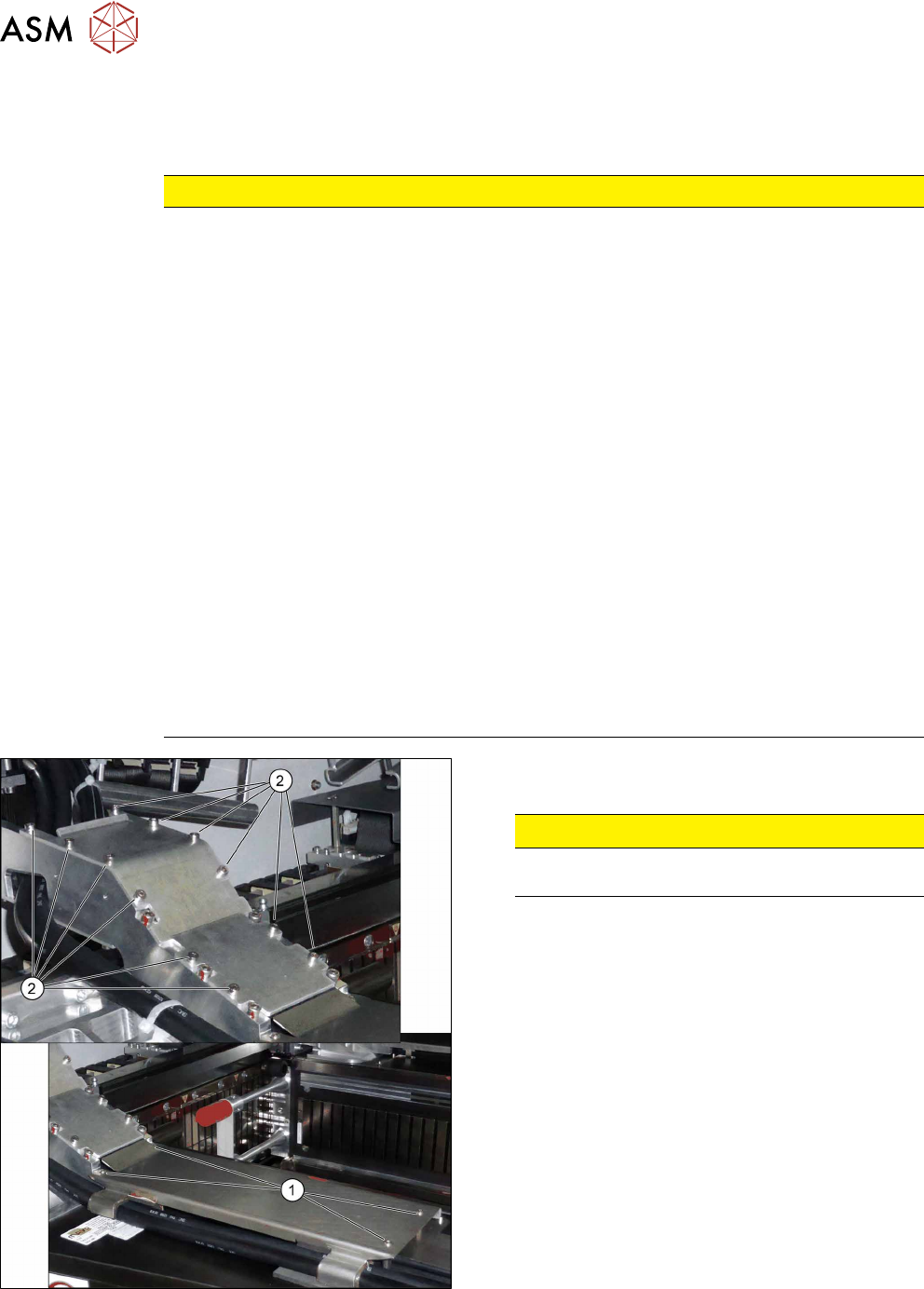
Fig.140: Covers
► Secure the screws(2) of the upper cover with
Loctite 241.
CAUTION!
Do not secure the screws(1) of the lower
cover with Loctite.
.