00198150-02_SM_TX_en.pdf - 第220页
8 Placement Heads and Stationary Cameras 8.6 Stationary Camera 220 Service Manual SIPLACE TX Series 06/2017 8.6.3 Troubleshooting Stationary Cameras Error / problem ● Errors arise during nozzle scanning, even though the …
8 Placement Heads and Stationary Cameras
8.6 Stationary Camera
Service Manual SIPLACE TX Series 06/2017 219
8.6 Stationary Camera
8.6.1 Replacing the Stationary Component Camera Digital Type 25/33/GigE
The following stationary cameras can be fitted to the SIPLACE TX-Series
●
Stationary camera type 25 TH SIPLACE TX [00588101-xx]
●
Stationary camera type 33 TH SIPLACE TX [00588100-xx]
► Read also the assembly instructions "Stationary Camera" [00198142-xx] (German and Eng-
lish).
See also
2 PCBs Stationary Cameras [}221]
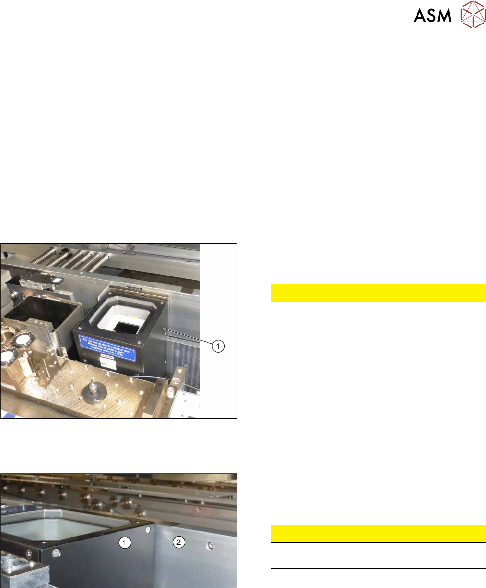
8.6.2 Checking the Installation Height of the Stationary Camera
Checking the installation height of the stationary camera type 25:
Fig.299: Positioning the upper part and checking the installation
height
► Check the installation height. The support plate
and the upper part(1) must be below the top
edge of the conveyor side.
CAUTION!
If the upper part protrudes too far, there is the
danger of a head crash.
.
► If an error occurs, read the corresponding assem-
bly instructions for more information.
Checking the installation height of the stationary camera type 33:
Fig.300: Checking the installation height
► Check the installation height.
When installed correctly, the upper part(1) is
2mm higher than the top edge of the conveyor
side(2).
CAUTION!
If the upper part protrudes too far, there is the
danger of a head crash.
.
► If an error occurs, read the corresponding assem-
bly instructions for more information.

8 Placement Heads and Stationary Cameras
8.6 Stationary Camera
220 Service Manual SIPLACE TX Series 06/2017
8.6.3 Troubleshooting Stationary Cameras
Error / problem
●
Errors arise during nozzle scanning, even though the nozzle has already been checked to en-
sure that it is clean.
●
During camera verification (FCCS), it is difficult to achieve the necessary illumination.
●
Increased component rejection rate, particularly with low-contrast components.
Cause of hazard
If one or more of these errors occurs, the cause may be a dirty camera.
Solution
► Clean the stationary cameras. Please read the technical information [DE: TI2014-10D09] [EN:
TI2014-10E09] for more information.
Problem
●
Error message 37752: "The LED test of the camera illumination failed" at GigE cameras
Solution
► Please contact the SIPLACE service team for more information.
Give them the following reference number: TI2015-08V03.
8 Placement Heads and Stationary Cameras
8.6 Stationary Camera
Service Manual SIPLACE TX Series 06/2017 221
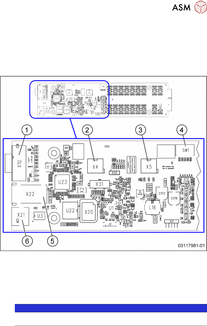
8.6.4 PCBs Stationary Cameras
8.6.4.1 Vision LED Controller VLC25/33 GigE DTC [03117981‑xx] [03117587‑xx]
The
Vision LED Controller VLC33 GigE DTC [03117981-xx] and
Vision LED Controller VLC25 GigE DTC [03117587-xx]
boards are identical, except for the connectors X21 and X22. These connectors are only present on
the VLC25 board.
The boards are part of the stationary camera SST25/33 GigE.
Fig.301: Vision LED Controller VLC25 GigE DTC [03117587-xx]
1 CAN bus 2 X4: Cable for power supply
3 X5: Cable for power supply, bridge to
FC camera
(Not used in TX-Series)
4 DIP switch SW1 (see below)
5 Connector X22 (VLC25 only) 6 Connector X21 (VLC25 only)
NOTICE
X21 and X22
The connectors X21 and X22 are not used in TX-Series machines.