00198150-02_SM_TX_en.pdf - 第276页
11 Cutter 11.14 Replacing the Solenoid Valves [03000630-xx] 276 Service Manual SIPLACE TX Series 06/2017 11.14 Replacing the Solenoid Valves [03000630-xx] Parts, equipment and tools Fig.391: Solenoid valve ● Solenoid va…
11 Cutter
11.13 Replacing the Throttle Valve [03000600-xx]
Service Manual SIPLACE TX Series 06/2017 275
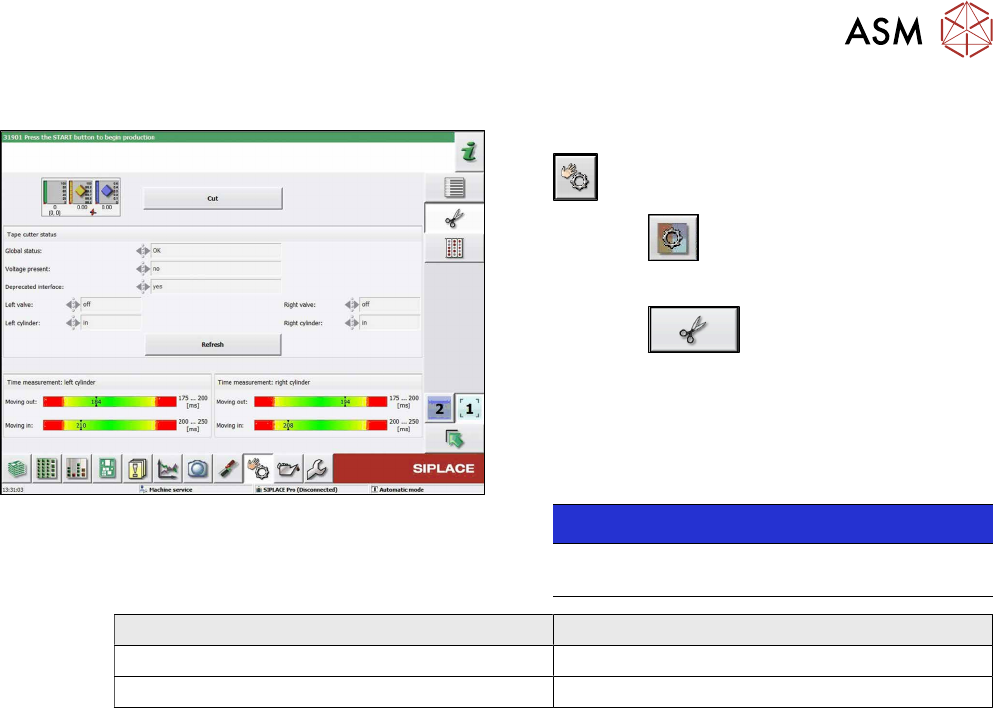
11.13.1 Times for Setting the Throttle on the Cutter (From SW707.1)
Fig.390: Measuring times
► Switch over to Check sensors and functions
.
► Select the
button.
► Select Location.
► Select the
button.
► Select Cut to start test.
You have to select the Cut button at least two
times (one for each side).
Repeat if necessary.
► Check the measured times.
NOTICE!
The permitted measurement ranges will be
provided by the software.
.
Cutter Time
Moving the blade out 175 to 200 ms
Moving the blade in 200 to 250 ms
► If necessary: Change the time by adjusting the throttle valves at the short-stroke cylinders.
11 Cutter
11.14 Replacing the Solenoid Valves [03000630-xx]
276 Service Manual SIPLACE TX Series 06/2017
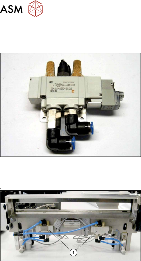
11.14 Replacing the Solenoid Valves [03000630-xx]
Parts, equipment and tools
Fig.391: Solenoid valve
●
Solenoid valve [03000630-xx]
Overview
Fig.392: Cutter
1. Position of the solenoid valves
Removal / installation
► Switch off the machine, disconnect it from the power supply and secure it to prevent
unauthorized reactivation. Observe the instructions in section 1.2 "Preparatory Work..." [}15].
► Loosen the compressed air connections on the solenoid valve.
► Unplug the press-fit connection on the solenoid valve connection cable. Mark the position to
make clear assignment easier later on.
► Remove the screws holding the solenoid valve in place and remove the solenoid valve.
► Mount the new solenoid valve and reestablish the press-fit connection to the valve.
► Plug in the compressed air connections.
► Attach cables ties if necessary (strain relief).
11 Cutter
11.15 Replacing the Silencer [00310744-xx]
Service Manual SIPLACE TX Series 06/2017 277
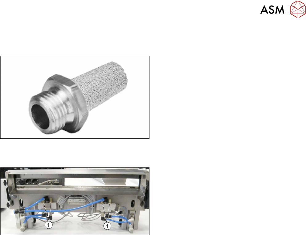
11.15 Replacing the Silencer [00310744-xx]
Parts, equipment and tools
Fig.393: Silencer
●
Silencer G-1/8 [00310744-xx]
Overview
Fig.394: Silencer on cutter
1. Silencer
The silencers are installed at the solenoid valves on
the lower side of the cutter.
Removal
► Switch off the machine, disconnect it from the power supply and secure it to prevent
unauthorized reactivation. Observe the instructions in section 1.2 "Preparatory Work..." [}15].
► Try to perform the exchange on the installed cutter.
If access is too limited, remove the cutter from the machine:
11.3 "Replacing the Cutter on the COT Insert [03066690-xx]" [}252]
► Remove the silencer with a SW13 spanner.
Installation
► Follow the removal instructions in reverse order for installation.