00198150-02_SM_TX_en.pdf - 第19页
1 Introduction 1.3 Other Instructions Service Manual SIPLACE TX Series 06/2017 19 1.3.6 Serial Number of the Machine Fig.6: Serial number The serial number of the machine can be found in two places. 1. On the typeplate …

1 Introduction
1.3 Other Instructions
18 Service Manual SIPLACE TX Series 06/2017
1.3.4.3 Handling ESD Modules
Do not touch electronic modules unless it is absolutely essential to do so in order to carry out other
work. If it is necessary, make sure that you do not touch the pins or printed conductors when you
pick up flat modules.
Do not touch components unless
●
You are constantly earthed by an ESD wrist strap or
●
You are wearing ESD shoes or ESD shoe earthing strips on an ESD floor.
Always discharge yourself before you touch an electronic module. To do this, simply touch a con-
ductive and earthed object immediately before you touch the module (such as unpainted parts of a
switch cabinet, a water pipe, etc.).
Do not allow modules with chargeable and highly insulating materials to touch one another, e.g.
plastic films, insulating table surfaces or items of clothing made from synthetic fibers.
Always place the modules on a conductive surface (table with an ESD coating, conductive ESD
foam, ESD bag or container).
Do not bring modules near visual display units, monitors or televisions. Keep them at least 10cm
away from the screen.
1.3.4.4 Measurements and Modifications to ESD Modules
Measurements of the assemblies may only be taken if
●
The measuring device has been grounded (e.g. via protective conductor) or
●
you discharge the measuring head before taking measurements with a potential-free measur-
ing device (e.g. by touching an unpainted metal part of the controller casing).
► Always use an earthed soldering iron if you carry out any soldering work.
1.3.4.5 Dispatching ESD Modules
► Always store modules and components in conductive packaging (e.g. metalized plastic bags
or metal sleeves) and dispatch them in conductive packaging.
► If the packaging is not conductive, place the modules in a conductive envelope before pack-
aging. Use conductive expanded rubber, ESD bags, domestic aluminum foil or paper, for ex-
ample.
► If the module has integral batteries, ensure that the conductive packaging does not touch or
short-circuit the battery terminals and, if necessary, first cover the terminals with insulating
tape or material.
1.3.5 Validity of Document
This document is valid for the following machine types:
●
SIPLACE TX Series
The work described in this manual is divided into modules, and to a large extent, it is identical for
all machine types:
●
If the work required for specific machines differs from the standard procedure, this will be in-
dicated with reference to the machine number, series and delivery state.
●
Illustrations are only shown as examples, for example, the illustration of a specific machine
type or a machine with different paint finish does not imply that the information following the il-
lustration only applies to the shown machine type.
Please read the circuit diagram folder for any electrical checks.
●
Detailed circuit diagrams folder for SIPLACE TX-Series (up to no. 499) [DE+EN: 00197933-
xx]
●
Detailed circuit diagrams folder for SIPLACE TX-Series (from no. 500) [DE+EN: 00198274-xx]
1 Introduction
1.3 Other Instructions
Service Manual SIPLACE TX Series 06/2017 19
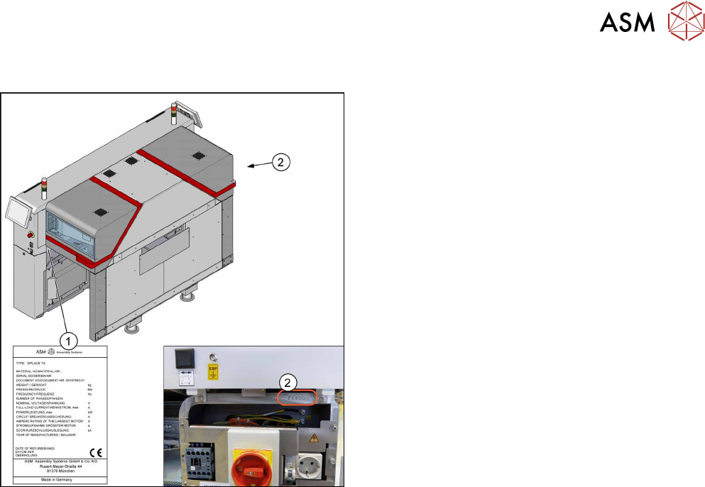
1.3.6 Serial Number of the Machine
Fig.6: Serial number
The serial number of the machine can be found in two
places.
1. On the typeplate on the inside of the machine
frame at location1.
2. Above the main switch at location 2 behind the
cover.

1 Introduction
1.3 Other Instructions
20 Service Manual SIPLACE TX Series 06/2017
1.3.7 Release History
Document
SIPLACE TX-Series
Service manual
Edition Changes
11/2016 First edition
06/2017 Upgrade
Amendments and supplements
●
Safety notes:
– Coplanarity module sensor (update)
– What to do before starting work (improved description)
●
Various new spare parts for micron machines
●
Basic machine:
– Gas pressure absorbers (improved description)
●
SMPS:
– Contactor safety breaker (CSB) (improved description)
●
Electrical system and control:
– Cover fan (new parts)
●
Pneumatic system:
– Overview of pneumatic system (improved description)
– Setting the compressed air controller (improved description)
●
Gantry:
– Replacing the X axis/mounting bracket incremental encoder (improved descrip-
tion)
– Replacing the Y axis/mounting bracket incremental encoder (improved descrip-
tion)
– Head adapter for the MHCU (washers)
– Head interface (improved description)
– Temperature sensor (gap filler)
– Sensor module (improved description)
– Replacing the filter element (O-ring (removed, will be described in the mainten-
ance manual)
●
Conveyor:
– Toothed belts for conveyor drives (improved description)
– Fiber optic cable sensor (improved description)
– Fiducial rail (new chapter)
– Vacuum tooling (new chapter)
●
Placement heads:
– SIPLACE C&P20 P/M2 (modification for GigE, improved description, supple-
ment for C&P20M2)
– SIPLACE CPP / CPP M (supplement for CPPM)
●
COT insert:
– Work on the COT insert without complete removal of this (new)
– Empty tape duct (new parts)
●
Cutter:
– Replacing the cutter (improved description)
– Spacer, metal buffer (improved description)
●
Docking station:
– Power pack (voltage setting)
●
JEDEC tray feeder:
– SIPLACE JTF-ML2 (new module)