00198140-01_UM_JTF-ML_TX12_de_en.pdf - 第89页
Setting up and Commissioning 4.2.6 Converting the Machine Protective Featu res Retrofitting in the SIPLACE TX-Series JEDEC Tray Feeder (JTF-ML) 89 4.2.6 4 . 2 . 6 C o n v e r t in g t h e M a c h in e P r o t e c t iv e …
Setting up and Commissioning
Retrofitting in the SIPLACE TX-Series 4.2.5 Converting the COT Insert
88 JEDEC Tray Feeder (JTF-ML)
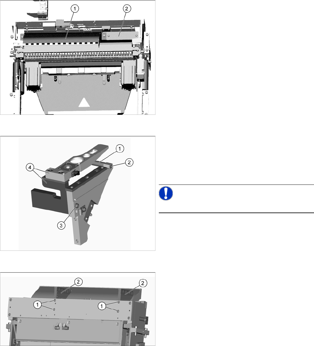
Fitting the empty-tape duct and cover
► Fit the short empty-tape duct (1), using two ISO4762-
M6x14-A2-70 [03043125-xx] screws.
► Fit the cover (2) using two ISO4762-M6x14-A2-70
[03043125-xx] screws.
Removing the NC holder
Perform the following steps on the dismantled NC holder:
► Remove the screw (2) fastening the support (1) and
remove this.
► Remove the screw (3) fastening the nozzle station
and the reject bin holder (4) and remove this.
NOTICE!
The previously used nozzle station is no longer needed.
Fitting the NC holder
► Fit the two NC holders (2) , with two screws in each
case (1).
Do not fit the NC yet.
Setting up and Commissioning
4.2.6 Converting the Machine Protective Features Retrofitting in the SIPLACE TX-Series
JEDEC Tray Feeder (JTF-ML) 89
4.2.6
4.2.6 Converting the Machine Protective Features
Converting the Machine Protective Features
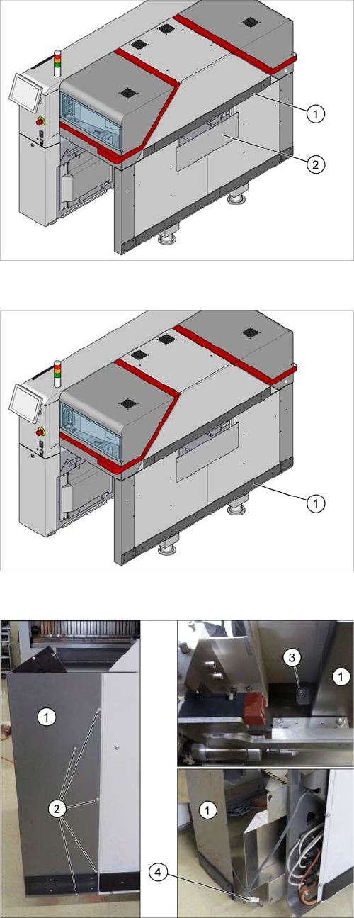
Removing the hand guard
1. Top rail with top hand guard below it
2. Bottom hand guard
► For removal of the following parts, read the relevant
section in the Assembly Instructions "Input and Out-
put Conveyor Extension SIPLACE TX"
[00198141-xx]
Removing the bottom rail
► Remove the bottom rail (1).
Removing the corner cover
Remove the corner cover (1). Proceed as follows:
► Remove the screws (2) on the outer side.
► Remove the screw (3) on the inner side.
Hold the corner cover firmly while doing this, so that
it does not accidentally fall down.
► Loosen the connector (4) and place the corner cover
to one side.
Setting up and Commissioning
Retrofitting in the SIPLACE TX-Series 4.2.6 Converting the Machine Protective Features
90 JEDEC Tray Feeder (JTF-ML)
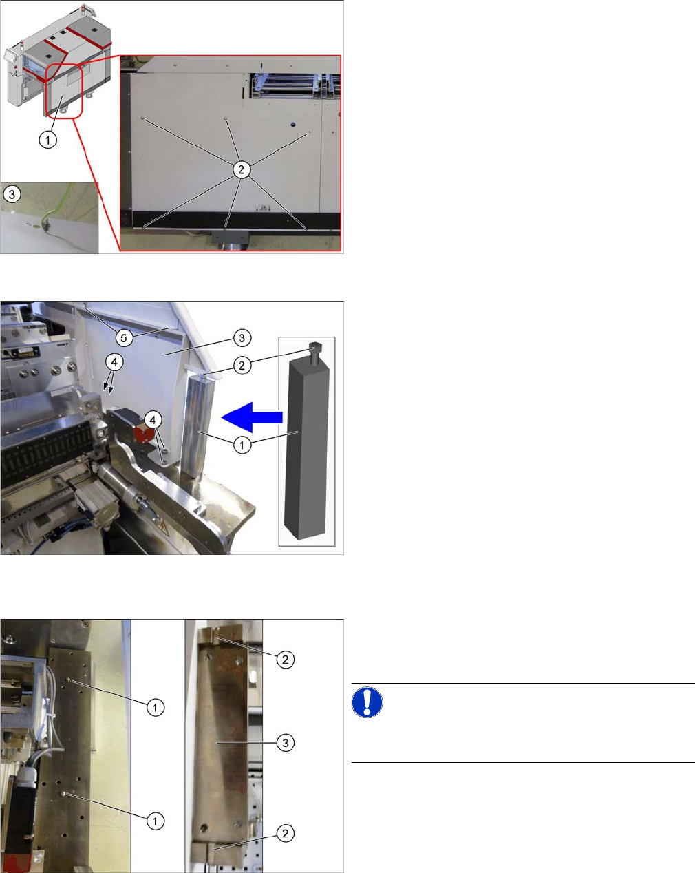
Removing the standard side cover
► Remove the six screws (2) fastening the standard
side cover (1).
Hold the standard side cover firmly while doing this,
so that it does not accidentally fall down.
► Loosen the ground cable (3) on the back of the stand-
ard side cover and place it to one side.
Inserting the support and remove the standard support
frame
► Insert the support [03136824-xx] (1) between the top
side cover and the machine frame.
► Tighten the screw (2) until the support is clamped
firmly into place.
► Remove the top two screws (5) fastening the stand-
ard support frame (3).
► Remove the bottom four screws (4) fastening the
standard support frame.
► Carefully remove the standard support frame from
the machine.
Knocking in the bolt
► Knock in the two centering pins [03015816-xx] (1).
These should protrude out of the base plate by
5mm+/- 0.5 mm.
NOTICE!
The cavities (2) on the JTF support frame (3) are 6 mm
deep.