00198140-01_UM_JTF-ML_TX12_de_en.pdf - 第94页
Setting up and Commissioning Retrofitting in the SIPLACE TX-Series 4.2.11 Preparing the Compo nent Trolley 94 JEDEC Tray Feeder (JTF-ML) 4.2.11 4 . 2 . 1 1 P r e p a r in g t h e C o m p o n e n t T r o lle y Preparing t…
Setting up and Commissioning
4.2.10 Fitting the SIPLACE JTF-ML Adapter Retrofitting in the SIPLACE TX-Series
JEDEC Tray Feeder (JTF-ML) 93
4.2.10
4.2.10 Fitting the SIPLACE JTF-ML Adapter
Fitting the SIPLACE JTF-ML Adapter
WARNING
Second person
We highly recommend that you enlist the help of a second person when fitting the SIPLACE
JTF-ML to the machine.
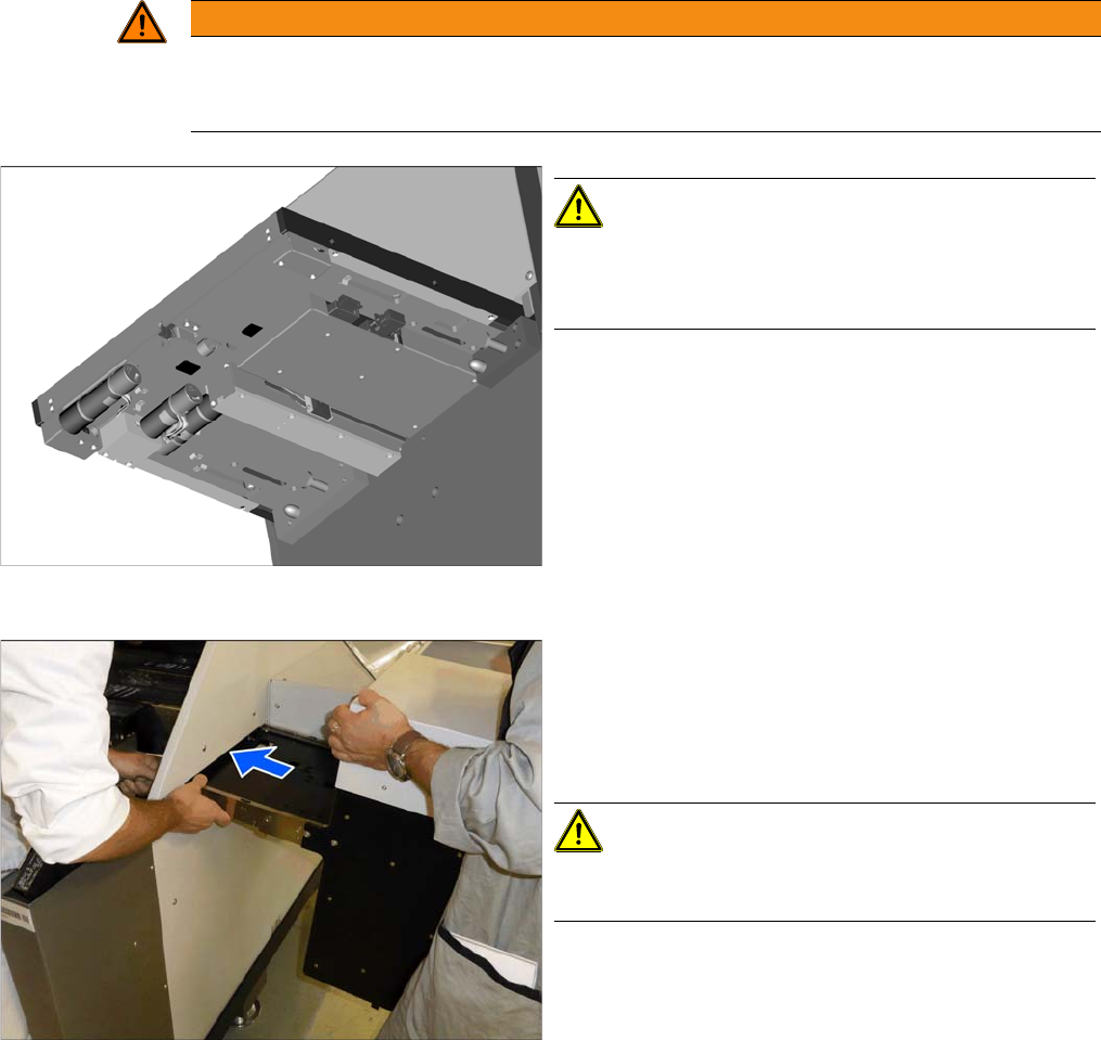
Underside of the SIPLACE JTF-ML
CAUTION!
The light barriers and other sensitive components are lo-
cated on the underside of the SIPLACE JTF-ML.
Make sure you do not damage these!
Inserting the SIPLACE JTF-ML
► Hold the SIPLACE JTF-ML as shown.
► Insert the SIPLACE JTF-ML into the machine. While
threading it through, make sure that you do not dam-
age the components on the underside of the
SIPLACE JTF-ML.
CAUTION!
Do not let go of the SIPLACE JTF-ML until it has been
fastened firmly to the holder (see next step).
Setting up and Commissioning
Retrofitting in the SIPLACE TX-Series 4.2.11 Preparing the Component Trolley
94 JEDEC Tray Feeder (JTF-ML)
4.2.11
4.2.11 Preparing the Component Trolley
Preparing the Component Trolley
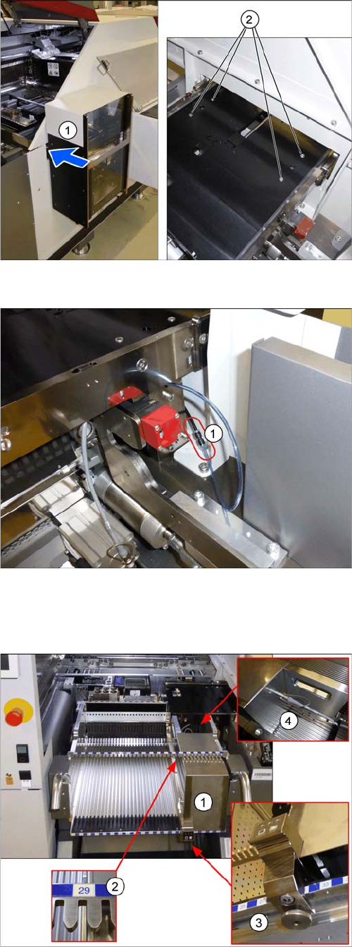
Mounting the SIPLACE JTF-ML
► Fasten the SIPLACE JTF-ML (1) to the holder with
four screws (2).
Connecting the compressed air hose
► Connect the compressed air hose (1).
Preparing the component trolley
► Fit the SIPLACE JTF-ML FDK (1) into place on track
29 (2) of the SIPLACE JTF component trolley.
► Lock the (3) SIPLACE JTF-ML FDK.
► Move the SIPLACE JTF component trolley into the
machine.
► Connect (4) the SIPLACE JTF-ML to the SIPLACE
JTF-ML FDK.
Setting up and Commissioning
4.2.12 Completing the Mechanical Work Retrofitting in the SIPLACE TX-Series
JEDEC Tray Feeder (JTF-ML) 95
4.2.12
4.2.12 Completing the Mechanical Work
Completing the Mechanical Work
► Check and correct the height of the NC holder (see "7.1.2.1 Setting the Nozzle Changer Height"
[ ➙ 120]).
► Check and correct the height of the nozzle changer (see "7.1.2.2 Setting the Height of the Nozzle
Station" [ ➙ 121]).
► Check the setting of the jumper on the NC (if one is present).
It must be set to 2-3 (see also "7.1.2.3 Jumpers on the Nozzle Changer" [ ➙ 122]).
► Fit the NC and the nozzle station.
► Install the used tape chute in location 1.
► Move the component trolley into the machine.
► Turn the machine on.
► Set the software (see "4.2.13 Software Settings" [ ➙ 95]).
4.2.13
4.2.13 Software Settings
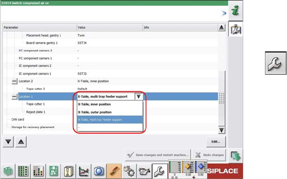
Software Settings
Configuring the SIPLACE JTF-ML
Configuration and calibration is performed in the user lev-
el Service.
► On first reboot with the SIPLACE JTF-ML, this needs
to be entered in the machine configuration. Select
Service → Machine Configuration.
► Select the SIPLACE JTF-ML at location 1.
► Save the changes.
► Reboot the machine.