00195376-05_SM_D1_D1i_D2_D2i_EN.pdf - 第101页
Service Work 4.3.10 Replacing the Stepping Motor of the Width Adjustment Syst em [00367174] PCB conveyor system Service Manual SIPLACE D1/D1i/D2/D2i 101 4.3.10 4 . 3 . 1 0 R e p la c in g t h e S t e p p in g M o t o r o…
Service Work
PCB conveyor system 4.3.9 Replacing the Lifting Table Fork Light Barrier [00363111]
100 Service Manual SIPLACE D1/D1i/D2/D2i
Installation
4.3.9
4.3.9 Replacing the Lifting Table Fork Light Barrier [00363111]
Replacing the Lifting Table Fork Light Barrier [00363111]
Parts
▪ Light barrier for track A (up) – single conveyor [00363111-xx]
▪ Light barrier for track B (down) – single conveyor [00363113-xx]
▪ Light barrier for track A (up) – dual conveyor [00363079-xx]
▪ Light barrier for track B (down) – dual conveyor [00363080-xx]
Removal/installation
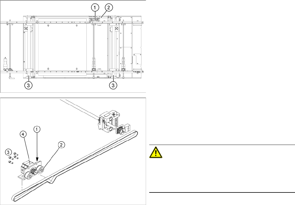
► Insert and fasten the new lifting table cylinder (2) and
install the piston rod (3).
► Move the lifting table by hand to its end position.
► Switch the machine on.
► Push the end position proximity switch (1) into the
guide rail until the LED lights up.
► Fix this position with the grub screw.
► Install the solenoid valve (4) and the lifting table plate.
Fasten any disconnected cables or hoses again, with
the cable ties.
► Check the speed of the lifting table and correct where
necessary.
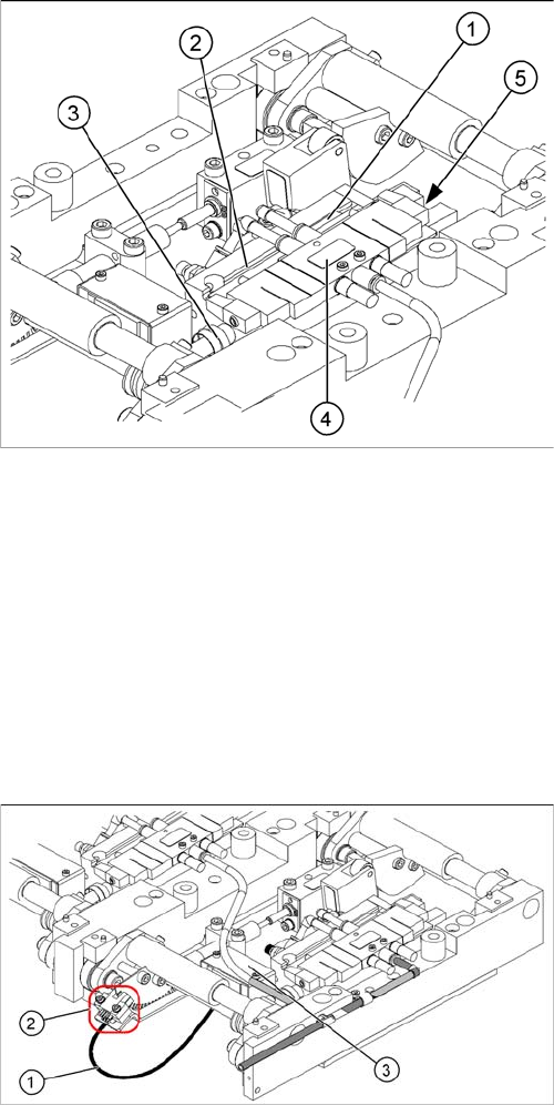
Legend
1. Connection cable for the conversion board of the lift-
ing table
2. 2 x fork light barrier (position measuring system,
tracks A + B)
3. Conversion board of the lifting table (under the cover)
► Move the PCB conveyor to the position which gives
you best access to the lifting table.
► Move the Y gantries into the area outside the PCB
conveyor.
► Switch off the machine and secure it to prevent unau-
thorized reactivation.
► Loosen the screws fastening the lifting table plate and
remove the lifting table plate from the lifting table unit.
► Loosen the two screws (2) fastening the fork light bar-
rier.
► Remove the cover from the conversion board of the
lifting table (3).
► Unplug the lifting table conversion board.
► Fit the new fork light barrier and reconnect to the
electrical system.
Service Work
4.3.10 Replacing the Stepping Motor of the Width Adjustment System [00367174] PCB conveyor system
Service Manual SIPLACE D1/D1i/D2/D2i 101
4.3.10
4.3.10 Replacing the Stepping Motor of the Width Adjustment System [00367174]
Replacing the Stepping Motor of the Width Adjustment System [00367174]
Overview
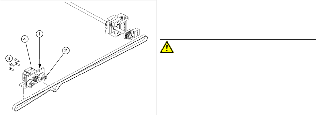
Legend
1. Width adjustment stepping motor
2. Toothed belt for the drive
3. Adjustment unit 1 and 2
Legend
1. Loosening the eccentric axle on the deflection pulley
2. Locknut on the eccentric axle
3. Fastening screws for stepping motor
4. Stepping motor [00367174-xx]
CAUTION!
Do not damage the toothed belt!
During the following removal and installation of the motor,
the toothed belt for the width adjustment drive must not
be stretched or kinked!
► Move the PCB conveyor to the position which gives
you best access to the stepping motor of the width
adjustment system.
► Move the Y gantries into the area outside the PCB
conveyor.
► Switch off the machine and secure it to prevent unau-
thorized reactivation.
Service Work
PCB conveyor system 4.3.10 Replacing the Stepping Motor of the Width Adjustment System [00367174]
102 Service Manual SIPLACE D1/D1i/D2/D2i
Removal/Installation
See also
6.7.1 Setting the Tension of the Conveyor Toothed Belt and the Width Adjustment Unit [ ➙ 261]
► Loosen the screws fastening the lifting table plate and
remove the lifting table plate from the lifting table unit.
► Loosen the eccentric axle (1) on the deflection pulley
and relieve the tension on the drive toothed belt (5).
CAUTION!
Parallelism of conveyor side: Toothed belt must not come
off!
When relaxing the toothed belt, make sure the belt does
not come off (skip) the toothed disks at the 2 adjustment
units. This would cause incorrect alignment of the adjust-
ment units. Secure these positions with a suitable tool
(screw clamp etc.)
► Remove the 4 fastening screws (3) and then lift out
the stepping motor (4).
► Unplug the connection cable in the cable duct.
► Fit the new stepping motor and reconnect the system
to the electrical system.
► Tension the drive toothed belt.
► Position the measuring point of the belt tension de-
vice at the strand center (i.e. the longest distance be-
tween two toothed disks) of the conveyor toothed
belt.
► Adjust the tension of the drive toothed belt.