00195376-05_SM_D1_D1i_D2_D2i_EN.pdf - 第28页
Overview Electrical System 3.2.3 Power Supply Unit 28 Service Manual SIPLACE D1/D1i/D2/D2i EMERGENCY STOP loops
Overview
3.2.3 Power Supply Unit Electrical System
Service Manual SIPLACE D1/D1i/D2/D2i 27
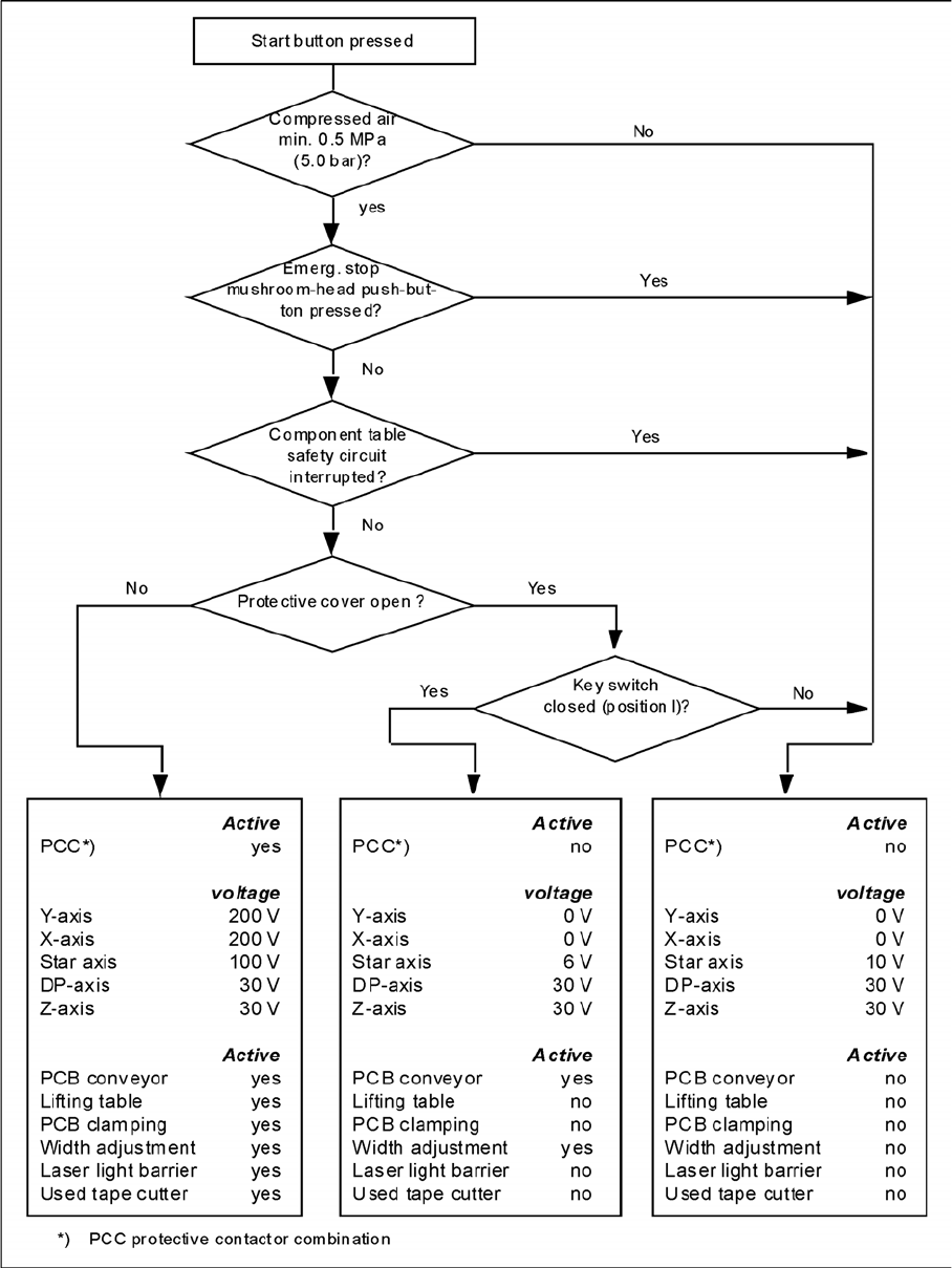
EMERGENCY STOP loop functions
The following conditions must be fulfilled before the placement system can be started or operated:
▪ All component trolleys must be docked in and connected.
▪ All protective covers must be closed.
▪ Both cover flaps over the PCB conveyor must be closed.
▪ Both emergency stop pushbuttons must be released.
▪ The emergency stop pushbutton on the WPC may need to be released.
▪ The two cover flaps (not available for D1, available as option for D2), located above the pushbuttons
and used to raise the changeover tables, must be closed.
▪ The minimum operating pressure must have been reached.
▪ The "software enable" signal must be active. This ensures that the EMERGENCY STOP loop is
closed.
▪ The power supply send 24 V to the start buttons and the protective contactor combination.
▪ If one of the start buttons is now pressed, the protective contactor combination PCC will switch and
activate the following components:
– 200 V link voltage for the servo amplifiers of the gantry axes
– 150 V link voltage for the star axes
– The axis unit will receive a "Servo Enable" signal for the servo amplifier.
– 34 V operating voltage is switched to the component trolleys.
– 24 V operating voltage is switched to the used tape cutters.
– The PCB conveyor control receives the enable signal for the PCB clamping, the PCB stopper
and the lifting table control.
The machine is then ready for use.
Overview
Electrical System 3.2.3 Power Supply Unit
28 Service Manual SIPLACE D1/D1i/D2/D2i
EMERGENCY STOP loops

Overview
3.2.3 Power Supply Unit Gantries
Service Manual SIPLACE D1/D1i/D2/D2i 29
3.3
3.3 Gantries
Gantries
Machine gantries (D2 shown here)
Legend
The D1 and D2 placement machines are equipped with one or two gantries. Using the Y-axis linear drive
and the X-axis belt drives, the gantries position the placement heads in the X and Y direction, above the
feeders and boards (PCBs).
The structure of the gantries makes them torsionally rigid and stable. The precise mechanical movement
of the axes is produced by axis recirculating ball screw units.
High-precision positioning systems determine the positions of the X and Y axes. To do this, the gradua-
tions on metal scales are optoelectronically scanned and the track signals are sent to the axis control in
the control unit.
1 Gantry 1 T Transport direction
2 Gantry 2 (for D2 only)
NOTICE
For an overview of the technical data for D-series machines, refer to "3.1 D-Series - General"
[ ➙ 19].