00195376-05_SM_D1_D1i_D2_D2i_EN.pdf - 第238页
Settings Collect&Place Head 6.5.9 Determin ing the Zero Point Correction f or the Star Axis of the C&P Head 238 Service Manual SIPLACE D1/D1i/D2/D2i 6.5.9 6 . 5 . 9 D e t e r m in in g t h e Z e r o P o in t C o …
Settings
6.5.8 Setting the Light Barrier Down Collect&Place Head
Service Manual SIPLACE D1/D1i/D2/D2i 237
6.5.8
6.5.8 Setting the Light Barrier Down
Setting the Light Barrier Down
Z end stopper check and adjust
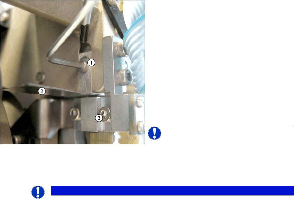
Legend
1. Z end stopper
2. Feeler gauge
3. Clamping device
► Loosen the Z axis end stopper screw.
► Clamp a 15/100 mm feeler gauge between the Z end
stopper and the clamp. Gently press the Z axis end
stopper downwards with the screwdriver and screw
tight.
► It should now be more difficult to extract the 15/
100 mm feeler gauge.
► Check again whether the 5/100 mm feeler gauge
passes easily (without resistance) between the Z axis
end position stop and the tension jack. If this is not the
case, you will need to readjust the setting!
NOTICE! When removing the gauge, make sure
that the gauge pin is extracted first and that then the star
gauge is removed. If you do not observe this order, the
gauge could catch in the segments and damage these!
NOTICE
The light barrier is set with a test probe to a distance of 1.0 mm to the sleeve.
Settings
Collect&Place Head 6.5.9 Determining the Zero Point Correction for the Star Axis of the C&P Head
238 Service Manual SIPLACE D1/D1i/D2/D2i
6.5.9
6.5.9 Determining the Zero Point Correction for the Star Axis of the C&P Head
Determining the Zero Point Correction for the Star Axis of the C&P Head
6.5.10
6.5.10 Adjustment of air pressure values
Adjustment of air pressure values
6.5.10.1
6.5.10.1 Tools and Equipment
Tools and Equipment
▪ A set of slotted screw drivers
▪ Compressed air testing device
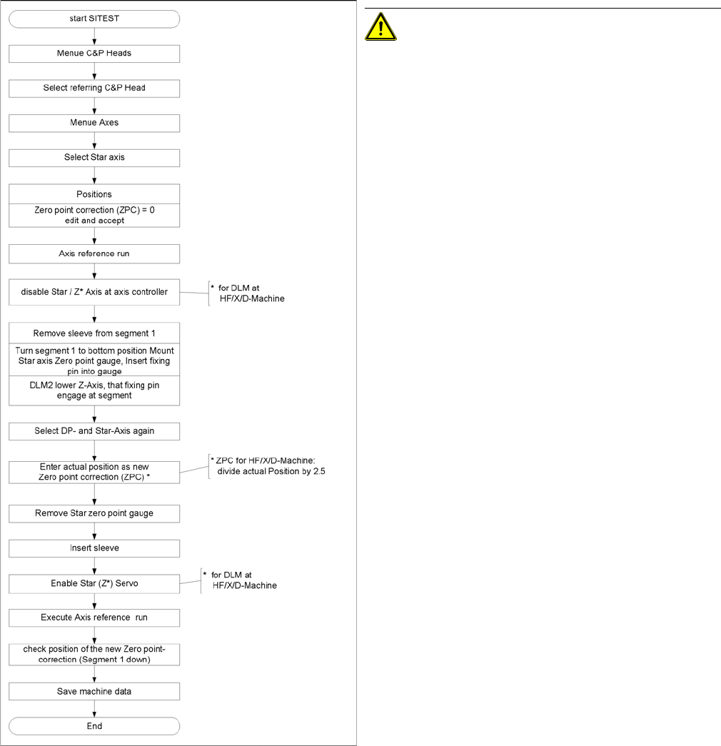
Flow chart zero point correction
CAUTION! When performing this task, follow all
instructions exactly!
Settings
6.5.10 Adjustment of air pressure values Collect&Place Head
Service Manual SIPLACE D1/D1i/D2/D2i 239
6.5.10.2
6.5.10.2 Setting the Air Blast Pressure Values
Setting the Air Blast Pressure Values
6.5.10.3
6.5.10.3 Setting the Air Blast Pressure Values with the Compressed Air Testing Device
Setting the Air Blast Pressure Values with the Compressed Air Testing Device
Adjust to the values of the table below:
Adjustment of air pressure values
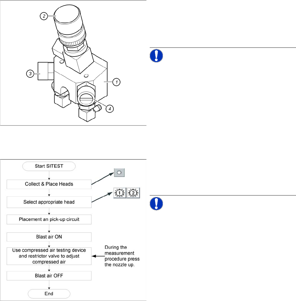
Legend
1. Forced air unit
2. Microswitch valve (new version with date stamp)
3. Adjustment valve for the reject circuit
4. Adjustment valve for the pick - up / placement circuit
NOTICE! Use a nozzle of type 914 to set the air
blast. Press in the spring on the nozzle interface during
the measurement and read the value from the display.
Flow chart determining air pressure values
When setting the air blast value with the compressed air
device and the adjustment valve, observe the following:
► Press the nozzle upwards during the measurement
process!!
NOTICE! The air blast values which are shown
in the Measured Air Blast menu, on the station computer
screen, at Single Functions or in the SITEST program, do
not reflect the air blast values really set at the nozzle.
They solely serve to check that the air blast valve is func-
tioning correctly. Therefore, do not use the values shown
on the screen to set the air blast. Instead, use only the
values determined with the compressed air testing de-
vice.