00195376-05_SM_D1_D1i_D2_D2i_EN.pdf - 第42页
Overview Changeover Table 3.5.6 Overview of Settings 42 Service Manual SIPLACE D1/D1i/D2/D2i 3.8 3 . 8 C h a n g e o v e r T a b le Changeover Table Overview: changeover tabl e structure (D1/D2) Legend Overview of Settin…
Overview
3.5.6 Overview of Settings Cutter
Service Manual SIPLACE D1/D1i/D2/D2i 41
3.7
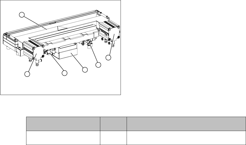
3.7 Cutter
Cutter
Overview
Overview of Settings
Legend
1. Tape cutter, pneumatic
2. Short-stroke cylinder
3. Control unit
4. Solenoid valves
2
4
1
4
3
2
Description Tools and
equipment
Values
Control unit jumper settings - See "6.9.1 Jumper setting on the control unit at the tape
cutter" [ ➙ 278].
Overview
Changeover Table 3.5.6 Overview of Settings
42 Service Manual SIPLACE D1/D1i/D2/D2i
3.8
3.8 Changeover Table
Changeover Table
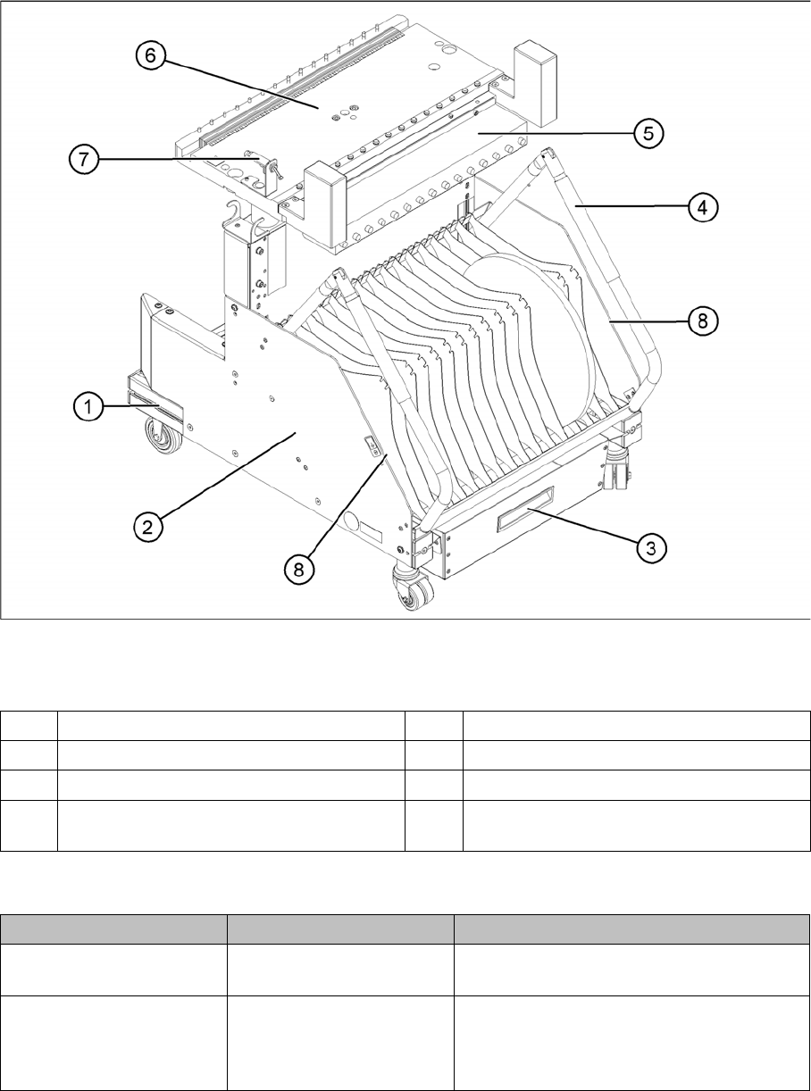
Overview: changeover table structure (D1/D2)
Legend
Overview of Settings
1 Moveable base with fixed and guide castor 5 Communication unit
2 Tape reels container 6 Table plate
3 Tape waste container 7 Switch for lowering the changeover table
4 Handle 8 Area for excess partition plates or setup
lists
Description Tools and equipment Values
Set up changeover tables
at machine height
Suitable lifting device and
eyebolt
See D1/D2 operating manual.
Move changeover table
supply line for location.
Changeover table option:
raising and lowering can
only be performed when the
table is docked.
Before the table is lowered, the table supply
line is attached to the required side of the ta-
ble. The table is then moved in, connected
and lowered.
Overview
3.8.1 Parts Overview Pneumatic Unit
Service Manual SIPLACE D1/D1i/D2/D2i 43
3.8.1
3.8.1 Parts Overview
Parts Overview
3.9
3.9 Pneumatic Unit
Pneumatic Unit
Overview of Settings
Quantity Designation Part No.
1 Changeover Table 03044856-xx
2 Double guide castor 03050704-xx
2 Fixed castor 03044881-xx
1 Communication unit for changeover table (Feeder Control Unit) 03002179-xx
1 Bellows cylinders 03044860-xx
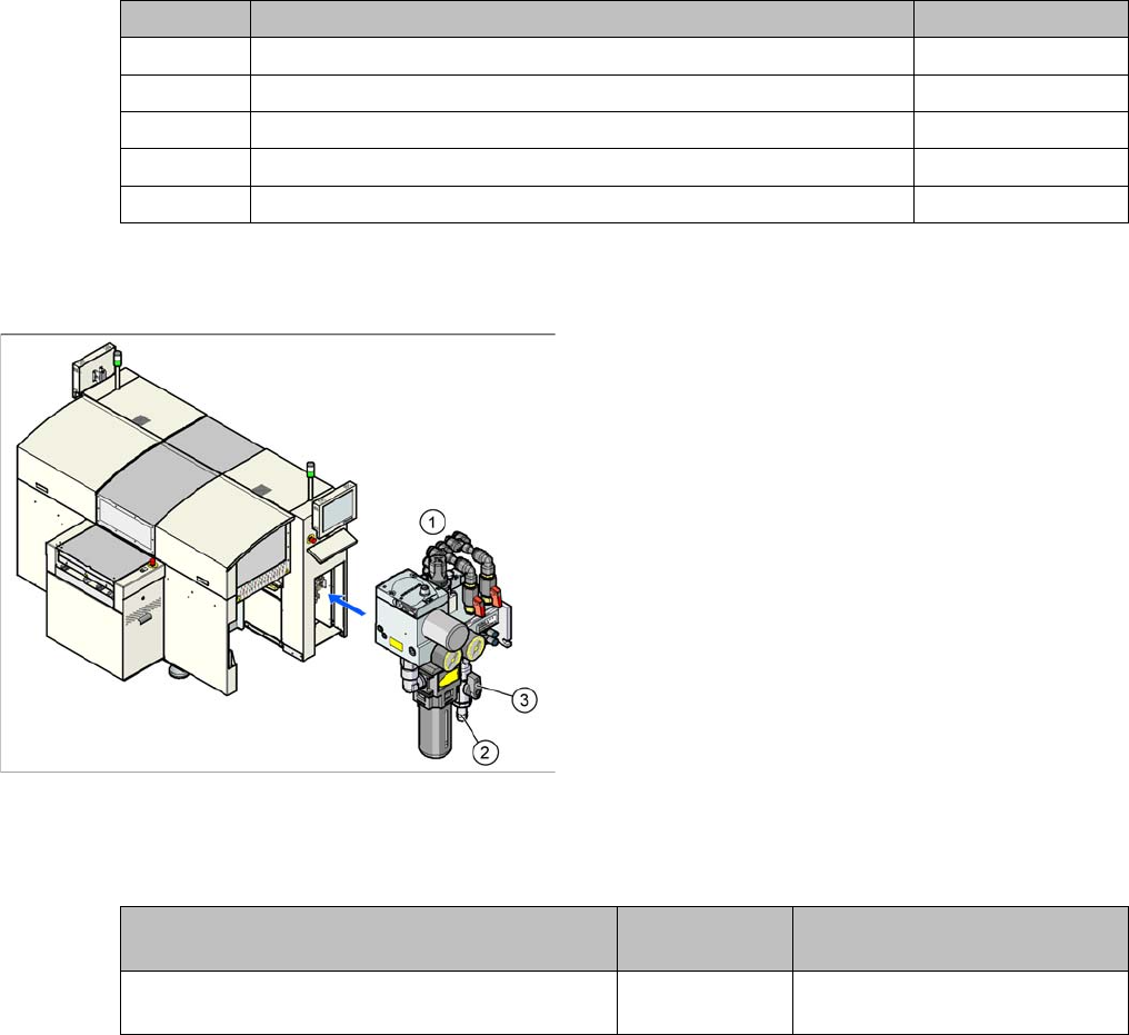
D1/D2 pneumatic unit
Legend
1. Pneumatic Unit
2. Compressed air connection coupling
3. Main stop valve
The pneumatic unit is mounted on a compact rack unit
and is located in the right-hand middle section of the ma-
chine. The unit has a lockable door to prevent unauthor-
ized access and contains the complete compressed air
supply, plus the SMEMA interface (Siemens) to the up-
stream and downstream stations.
Description Tools and equip-
ment
Values
Set compressed air supply to bulkcase feeder
manually
--- Typically 2.5 bar