00195376-05_SM_D1_D1i_D2_D2i_EN.pdf - 第44页
Overview Pneumatic Unit 3.8.1 Parts Overview 44 Service Manual SIPLACE D1/D1i/D2/D2i
Overview
3.8.1 Parts Overview Pneumatic Unit
Service Manual SIPLACE D1/D1i/D2/D2i 43
3.8.1
3.8.1 Parts Overview
Parts Overview
3.9
3.9 Pneumatic Unit
Pneumatic Unit
Overview of Settings
Quantity Designation Part No.
1 Changeover Table 03044856-xx
2 Double guide castor 03050704-xx
2 Fixed castor 03044881-xx
1 Communication unit for changeover table (Feeder Control Unit) 03002179-xx
1 Bellows cylinders 03044860-xx
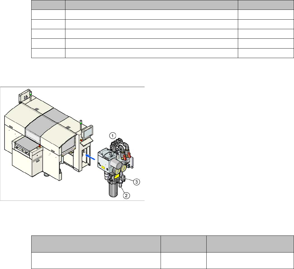
D1/D2 pneumatic unit
Legend
1. Pneumatic Unit
2. Compressed air connection coupling
3. Main stop valve
The pneumatic unit is mounted on a compact rack unit
and is located in the right-hand middle section of the ma-
chine. The unit has a lockable door to prevent unauthor-
ized access and contains the complete compressed air
supply, plus the SMEMA interface (Siemens) to the up-
stream and downstream stations.
Description Tools and equip-
ment
Values
Set compressed air supply to bulkcase feeder
manually
--- Typically 2.5 bar
Overview
Pneumatic Unit 3.8.1 Parts Overview
44 Service Manual SIPLACE D1/D1i/D2/D2i

Service Work
4.1.1 Power Supply Unit Electrical System
Service Manual SIPLACE D1/D1i/D2/D2i 45
4
4 Service Work
Service Work
4.1
4.1 Electrical System
Electrical System
4.1.1
4.1.1 Power Supply Unit
Power Supply Unit
4.1.1.1
4.1.1.1 Measuring Voltages on the Power Supply Unit
Measuring Voltages on the Power Supply Unit
Safety Instructions
Tools and equipment required
▪ Digital voltmeter, class 1.5
Measurement range:
– AC voltage: 750 V
– Alternating current: 40 A
– DC voltage: 300 V
– Direct current: 30 A
– Resistance: 200 Ohm - 20 MOhm
▪ Test cable with test probes or terminals
▪ Detailed circuit diagrams for SIPLACE D1/D2 [German: 0194841-xx] [English: 0194842-xx]
▪ DIN 911 Allen key, size 6
▪ 3 mm key, double-bit, DIN 43668-J33 (00304191-xx)
Preparing the power supply unit for measurement
The power supply unit and main switch are located in the machine frame. In front of the unit there is a
set of safety doors which can be opened with the double-bit key.
The unit is fixed to the machine frame using an M8 hexagon socket-head screw.
To measure the power supply, proceed as follows:
DANGER
The machine is supplied with 3 x 400 V~ (or 3 x 204 V~ / 3 x 230 V~ / 3 x 380 V~ / 3 x 415 V~)
± 5 %, 50/60 Hz mains voltage.
Consequently, parts of the system carry potentially lethal voltages, even when it is switched off
at the main switch.
Incorrect handling of the placement system can therefore result in death, severe injury or con-
siderable damage to equipment.
Measurements and repairs must always be carried out by appropriately qualified personnel.
► Observe the safety instructions in section.
► Always follow the applicable accident prevention and VDE regulations (particularly DIN EN
60 204, part 1) or the regulations specific to your country.