00195376-05_SM_D1_D1i_D2_D2i_EN.pdf - 第52页
Service Work Electrical System 4.1.1 Power Supply Unit 52 Service Manual SIPLACE D1/D1i/D2/D2i ▪ 3 x 8.14 VAC ▪ 3 x 32.5 VAC ▪ 3 x 32.5 VAC ▪ 3 x 24.4 VAC Terminal panel of the power supply unit Terminal panel of the pow…
Service Work
4.1.1 Power Supply Unit Electrical System
Service Manual SIPLACE D1/D1i/D2/D2i 51
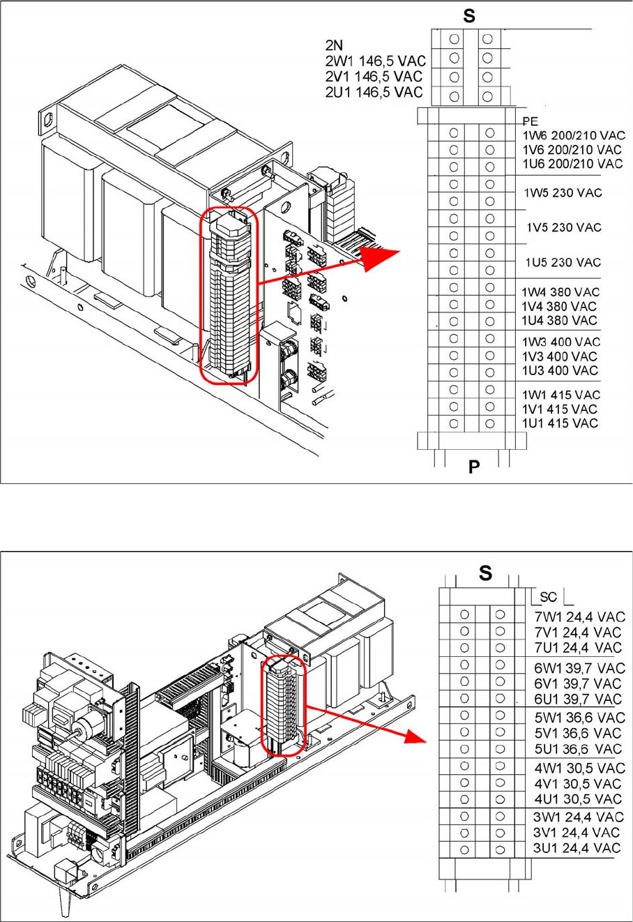
Primary terminals of transformer T1
Secondary side of transformer T1
Secondary terminals of transformer T1
Transformer T1 supplies the following voltages on the secondary side:
▪ 3 x 24.4 VAC
▪ 3 x 40.7 VAC
Service Work
Electrical System 4.1.1 Power Supply Unit
52 Service Manual SIPLACE D1/D1i/D2/D2i
▪ 3 x 8.14 VAC
▪ 3 x 32.5 VAC
▪ 3 x 32.5 VAC
▪ 3 x 24.4 VAC
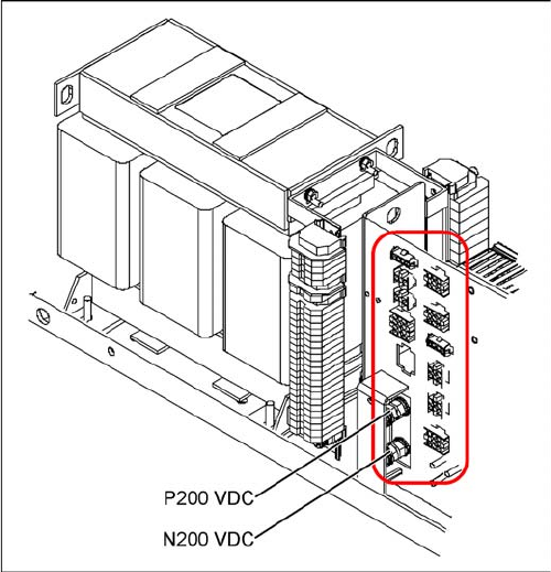
Terminal panel of the power supply unit
Terminal panel of the power supply unit
▪ T1: 11.1 kVA three-phase transformer
▪ X14: P200 V - screwed connection M6 (+) for supply-
ing the X/Y axis servo amplifier
▪ X15,16,17, EEP: N200 V - screwed connection M8/
M6 (-) for supplying the X/Y axis servo amplifier
▪ X2: To the monitor 1, 2
▪ X3: Box PC
▪ X4: Micro Box PC
▪ X5: Main distributor/subdistributor (regulated voltage)
▪ X6: PCB conveyor
▪ X7: Subdistributor (unregulated voltage)
▪ X8: Axis unit
▪ X10: Main distributor (unregulated voltage)
▪ X12: From/to the main distributor, (control signals,
power supply)
▪ X13: From/to the main distributor, (PCC peripherals)
The pin assignments of the individual plugs are shown in
the detailed circuit diagrams in section 3 "Circuit dia-
grams".
Service Work
4.1.2 Replacing the Complete Axis Unit Electrical System
Service Manual SIPLACE D1/D1i/D2/D2i 53
4.1.2
4.1.2 Replacing the Complete Axis Unit
Replacing the Complete Axis Unit
Axis unit DIP switch
4.1.3
4.1.3 Replacing the Axis Unit with Adapter Cable (X, D Series)
Replacing the Axis Unit with Adapter Cable (X, D Series)
Parts, equipment and tools
▪ Axis unit A364 replacement kit [03050365S02]
This contains the following parts:
– Axis unit A364 [03050365-02]
– Adapter cable harness for axis unit [03050590-01]
– 2 DIN912-M3 x 6-A2-70 screws [00201463-xx]
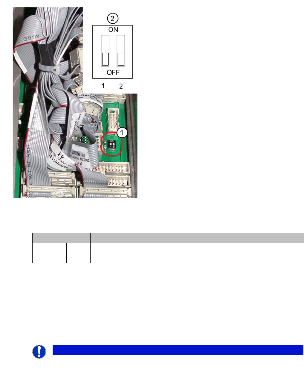
DIP switch on the backplane
► End all placement operations with the machine.
► Switch the placement system off at the main switch.
► Open the axis unit.
Legend
1. Position of DIP switch on the backplane
2. Setting for axis unit
shown here for axis unit 1
If the axis unit has been replaced, you will need to config-
ure the jumper setting (2).
S Axis unit 1 Axis unit 2 Comments
1OFF ON Axis unit 1 for SIPLACE D1/D2, D3, D4
2OFF ON Axis unit 2 only for SIPLACE D3, D4
NOTICE
Adapter cable harness
The adapter cable harness is only needed when an old axis unit is replaced with a new one.