00195376-05_SM_D1_D1i_D2_D2i_EN.pdf - 第105页
Service Work 4.3.13 Replacing the Cylinder Swi tch for the Adju stment Unit [0 3040796-xx] (a pplicable to modular P CB conveyor only) PCB convey or system Service Manual SIPLACE D1/D1i/D2/D2i 105 Removal/installation 4.…
Service Work
PCB conveyor system 4.3.12 Replacing the Solenoid Valve for the Adjustment Unit [00332940-xx]
104 Service Manual SIPLACE D1/D1i/D2/D2i
Removal/installation
4.3.12
4.3.12 Replacing the Solenoid Valve for the Adjustment Unit [00332940-xx] (applicable to modular PCB conveyor only)
Replacing the Solenoid Valve for the Adjustment Unit [00332940-xx] (applicable to
modular PCB conveyor only)
Overview
► Adjust the conveyor width, so that the required limit
switches can be easily accessed.
NOTICE!
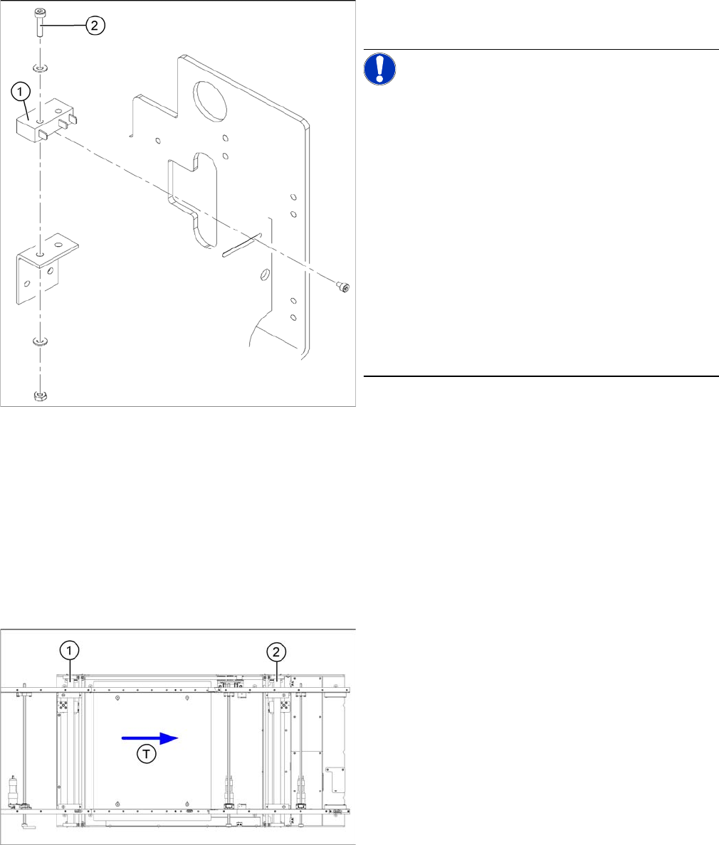
The limit switches are preassembled and include cables.
However, if the limit switch itself is faulty, the wiring can
be unsoldered/soldered right at the switch in question.
Remove the heat-shrinkable sleeves and unsolder the
connection wires on the defective limit switch (1).
Loosen and remove the two screws (2) fastening the de-
fective limit switch.
If you have discovered a break in the connection cable
during a continuity check, this cable must be unthreaded
as far as the conversion board of the assembly tub and
unplugged there.This might be somewhat complicated
depending on the routing of cables inside the machine
base.
You may wish to contact SIPLACE service team regard-
ing this work.
► Fit the new limit switch and re-solder the connection
wires in the correct allocation.
Checking the position of the limit switch:
► Check the minimum and maximum width of the rele-
vant machine type and the parallelism of the convey-
or edges.
Parts
▪ Solenoid valve with cable, for adjustment unit 1 and 2
[00332940-xx]
Legend
1. Adjustment unit 1
2. Adjustment unit 2
▪ T = transport direction
Service Work
4.3.13 Replacing the Cylinder Switch for the Adjustment Unit [03040796-xx] (applicable to modular PCB conveyor only) PCB conveyor system
Service Manual SIPLACE D1/D1i/D2/D2i 105
Removal/installation
4.3.13
4.3.13 Replacing the Cylinder Switch for the Adjustment Unit [03040796-xx] (applicable to modular PCB conveyor only)
Replacing the Cylinder Switch for the Adjustment Unit [03040796-xx] (applicable to
modular PCB conveyor only)
Overview
The cylinder switch on the adjustment unit cylinder should operate when the adjustment unit pin is
pushed out by the pneumatic cylinder and therefore connected to the conveyor side. This signal enables
the width adjustment motor.
► Move the PCB conveyor to the position which gives
you best access to the adjustment system.
► Move the Y gantries into the area outside the PCB
conveyor.
► Switch off the machine and secure it to prevent unau-
thorized reactivation.
► Switch off the compressed air supply.
► Position the width adjustment belt of the adjustment
unit so that the solenoid valve can be easily ac-
cessed.
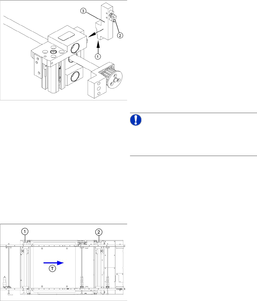
► Remove the compressed air connections (2).
► Loosen the two fastening screws and remove the so-
lenoid valve (3) from the short-stroke cylinder.
► Unthread the connection cable (1) as far as the rele-
vant assembly tub conversion board and unplug.
NOTICE!
This might be somewhat complicated depending on the
routing of cables inside the machine base.
You may wish to contact SIPLACE service team regard-
ing this work.
► Fit the new solenoid valve (3) and reconnect the sys-
tem to the electrical (1) and compressed air (2) sup-
plies.
Parts
▪ Cylinder switch of width adjustment 1 and 2
[03040796-xx]
Legend
1. Adjustment unit 1
2. Adjustment unit 2
▪ T = transport direction
Service Work
PCB conveyor system 4.3.13 Replacing the Cylinder Switch for the Adjustment Unit [03040796-xx]
106 Service Manual SIPLACE D1/D1i/D2/D2i
Removal/Installation
► Move the PCB conveyor to the position which gives
you best access to the adjustment system.
► Move the Y gantries into the area outside the PCB
conveyor.
► Switch off the machine and secure it to prevent unau-
thorized reactivation.
► Switch off the compressed air supply.
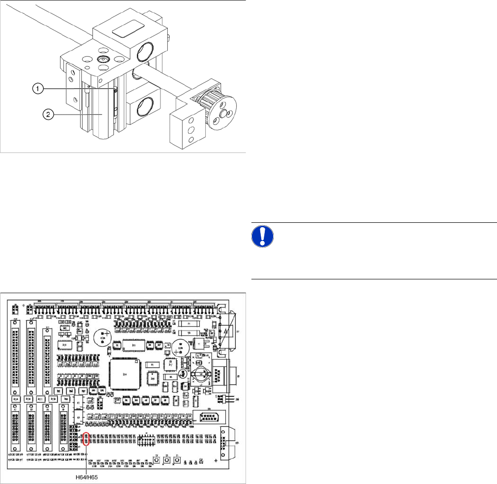
► Loosen the grub screw at the cylinder switch (1) and
push the cylinder switch out of the adjustment unit
guide rail (2).
► Unthread the connection cable as far as the conver-
sion board of the assembly tub.
► Run the connection cable of the new cylinder switch.
► Insert the new cylinder switch into the guide rail.
► Switch the machine on.
NOTICE!
The width adjustment system cylinder switch is set in en-
gaged mode.
TSP201
► Move the width adjustment system until the cylinder
switch switches - LED (H64/H65).
Engage the cylinder - i.e. the cylinders are moved to
the upper limit by the controls.
► Set the cylinder switch so that the LED lights up when
it is in engaged mode.
► Fix the position of the cylinder switch (2) with the grub
screw.