00195376-05_SM_D1_D1i_D2_D2i_EN.pdf - 第82页
Service Work Gantries 4.2. 15 Trailing Cable Interface [03043687- xx] 82 Service Manual SIPLACE D1/D1i/D2/D2i Removal/Installation 4.2.15 4 . 2 . 1 5 T r a ilin g C a b le I n t e r f a c e [ 0 3 0 4 3 6 8 7 - x x ] Trai…
Service Work
4.2.14 Replacing the Gantry Distributor [03035888-XX] Gantries
Service Manual SIPLACE D1/D1i/D2/D2i 81
Installation
4.2.14
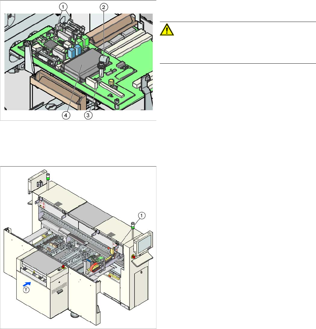
4.2.14 Replacing the Gantry Distributor [03035888-XX]
Replacing the Gantry Distributor [03035888-XX]
Overview
► Installation is performed by following the above in-
structions in reverse order.
CAUTION! Cable clamps for the flat ribbon ca-
ble
Make sure you fit the cable clamps for the flat ribbon ca-
ble, as this provides the ground connection.
► Check the jumper setting for the gantry coding. (See
section.)
Legend
1. Gantry distributor (behind the cover)
Service Work
Gantries 4.2.15 Trailing Cable Interface [03043687-xx]
82 Service Manual SIPLACE D1/D1i/D2/D2i
Removal/Installation
4.2.15
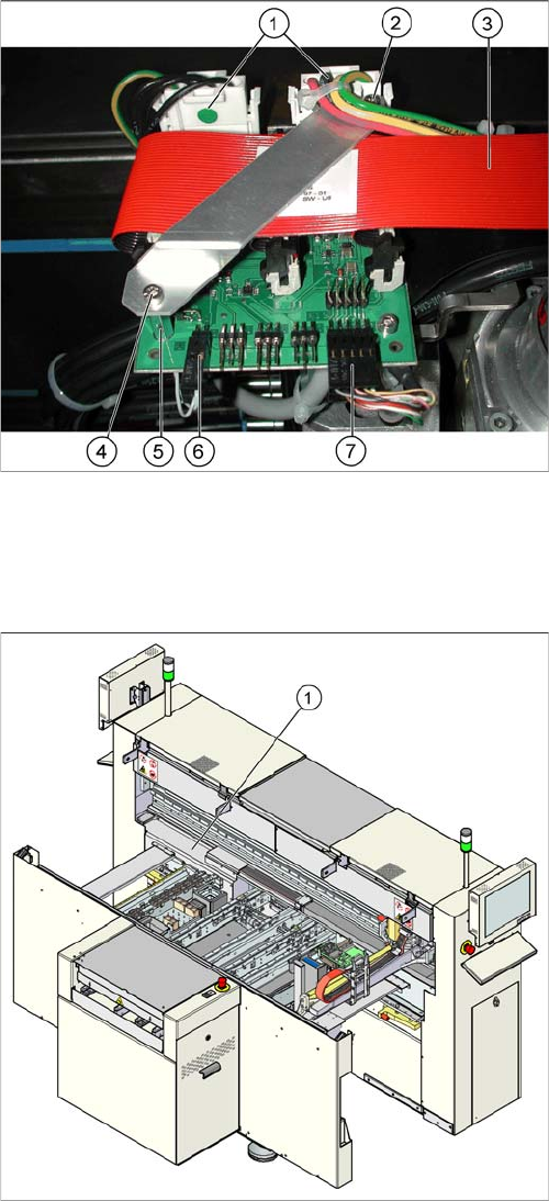
4.2.15 Trailing Cable Interface [03043687-xx]
Trailing Cable Interface [03043687-xx]
Removal/Installation
► Switch off the machine.
► Loosen the two screws (4) fastening the flat ribbon
cable holder (2).
► Loosen all electrical connections (1, 3, 6, 7) and label
their positions for easier reconnection, later.
► Detach the two supports for the flat ribbon cable hold-
er (5) and remove the two screws.
► Remove the board and fit the new one by following
the above instructions in reverse order.
Parts
▪ Trailing cable interface [03043687-xx] (D1, D2)
▪ Trailing cable interface [03043686-xx] (D1, D2)
Legend
1. Trailing cable interface for sector 1 (cable host carrier
distributor) (under the cover)
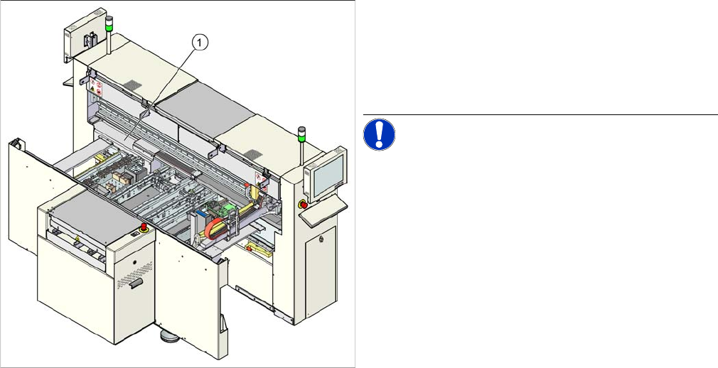
► Remove the cover from the relevant machine side.
► Loosen all electrical connections and label their posi-
tions clearly, for easier reconnection, later.
► Unplug the connections to the Hotlink card, if this
gives you better access. Label the positions for easier
reconnection, later.
► Loosen the eight screws fastening the board and re-
move the board.
► Fit the new board by following the above instructions
in reverse order.
Service Work
4.2.16 Hotlink Filter Card [03010670-xx] Gantries
Service Manual SIPLACE D1/D1i/D2/D2i 83
4.2.16
4.2.16 Hotlink Filter Card [03010670-xx]
Hotlink Filter Card [03010670-xx]
Removal/Installation
Legend
1. Hotlink filter card (under the cover)
► Remove the cover.
► Loosen all electrical connections and label their posi-
tions clearly, for easier reconnection, later.
NOTICE! Take care while opening the connec-
tions to the SIPLACE Vision system.
► Loosen the four hexagon socket-head screws, fas-
tening the board and remove the board.
► Fit the new board by following the above instructions
in reverse order.