00195376-05_SM_D1_D1i_D2_D2i_EN.pdf - 第92页
Service Work PCB conveyor system 4.3.3 Repla cing the Toothed Belt of the Driv e Unit [00355 553] 92 Service Manual SIPLACE D1/D1i/D2/D2i Removal/installation ► Mo ve the conv eyor to a suitable width, so that the drive …
Service Work
4.3.3 Replacing the Toothed Belt of the Drive Unit [00355553] PCB conveyor system
Service Manual SIPLACE D1/D1i/D2/D2i 91
Installation
4.3.3
4.3.3 Replacing the Toothed Belt of the Drive Unit [00355553]
Replacing the Toothed Belt of the Drive Unit [00355553]
Overview
CAUTION!
Do not damage the toothed belt!
The toothed belts must not be stretched or kinked!
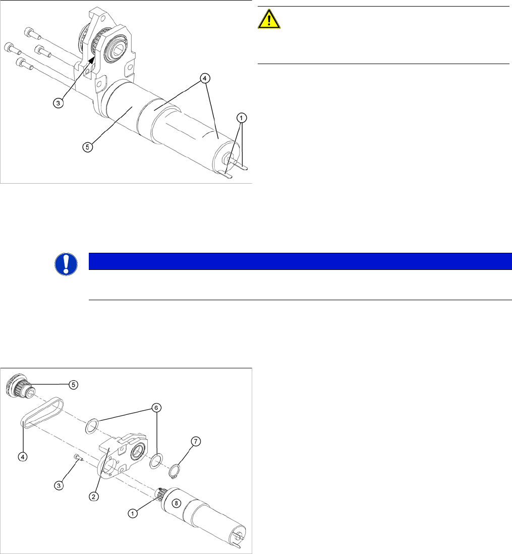
► Insert the new DC geared motor (5) by following the
instructions in reverse order.
The entire width of the toothed belt (3) must engage
at the top and bottom toothed disks.
► Fix the DC geared motor (5) with the 4 M3 hexagonal
socket-head screws (2).
► Tension the toothed belt (3) by moving the DC geared
motor in the fastening holes. (See "6.7.1 Setting the
Tension of the Conveyor Toothed Belt and the Width
Adjustment Unit" [ ➙ 261].)
► Reconnect to the electrical system (1) and secure the
connection cable with a heat-shrinkable hose (4).
NOTICE
► After the new drive has been installed, check the direction of rotation (polarity) and the con-
veyor speed with SITEST.
Required tools
▪ Circlip pliers
Legend
1. Toothed disk of motor
2. Motor mount
3. 4 x fastening screws
4. Toothed belt
5. Toothed disk of drive shaft
6. Shim/washers
7. Circlip
8. DC geared motor
The DC geared motors, including the motor mounts of all
3 conveyor areas, are of like construction. Please bear in
mind the following differences during assembly and dis-
assembly:
▪ The motor mount is installed either horizontally or
vertically, according to the requirements of the instal-
lation site.
Service Work
PCB conveyor system 4.3.3 Replacing the Toothed Belt of the Drive Unit [00355553]
92 Service Manual SIPLACE D1/D1i/D2/D2i
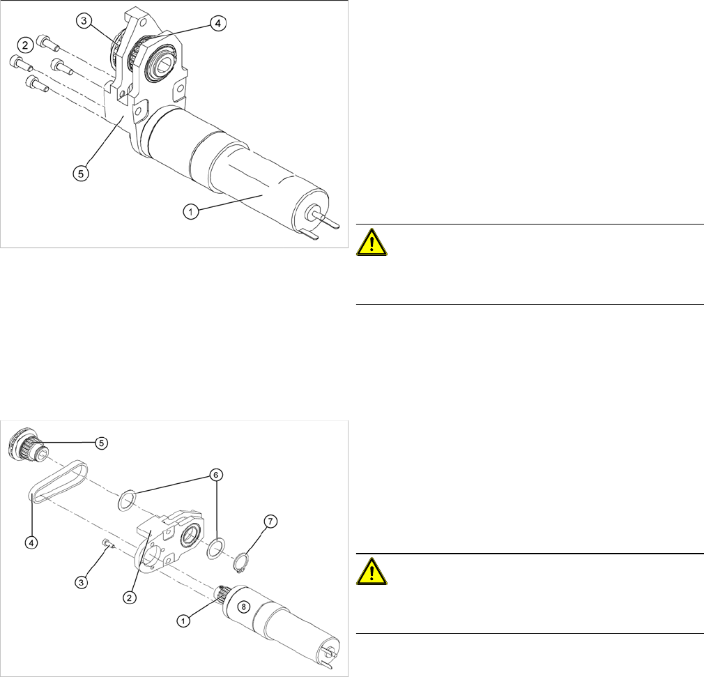
Removal/installation
► Move the conveyor to a suitable width, so that the
drive unit can be easily accessed and then move the
gantry out of the working area.
► Switch off the machine and secure it to prevent unau-
thorized reactivation.
► Remove the complete drive unit (5).
► Loosen the screws (2) holding the DC geared motor
(1).
► Tilt the DC geared motor (1) with its toothed disk (4)
a little, so that the small toothed belt comes free of the
toothed disk.
CAUTION!
Do not damage the toothed belt!
The toothed belts must not be stretched or kinked!
► Pull the DC geared motor out.
► Please observe:
the toothed disk on the motor shaft must be moved
out in such a manner that it does not get caught in the
toothed belt.
► Remove the circlip (7) and the shim rings (6).
► Use a small rubber mallet to carefully knock the
toothed disk (5) out of the motor mount (2).
► Remove the toothed belt (4) from the mount.
► Carefully unthread the toothed belt through the open-
ings above the hexagonal shaft.
CAUTION!
Do not damage the toothed belt!
The toothed belts must not be stretched or kinked!
► Insert the new toothed belt (4) through the openings
in the motor mount (2) and place the belt around the
toothed disk (1) of the motor.
Service Work
4.3.4 Replacing the Conveyor Toothed Belt [00359917-xx] PCB conveyor system
Service Manual SIPLACE D1/D1i/D2/D2i 93
4.3.4
4.3.4 Replacing the Conveyor Toothed Belt [00359917-xx]
Replacing the Conveyor Toothed Belt [00359917-xx]
Overview
► Place the toothed belt around the toothed disk (5) of
the drive shaft and insert the toothed disk into its
mount.
► Use a rubber mallet to carefully knock the toothed
disk into position.
► Fit the shim rings (6) and the circlip (7).
► Loosely fasten the DC geared motor (8) with the 4 M3
hexagonal socket-head screws (3). The entire width
of the toothed belt must engage at the top and bottom
toothed disks.
► Tension the toothed belt (4) by moving the DC geared
motor in the fastening holes. (See "6.7.1 Setting the
Tension of the Conveyor Toothed Belt and the Width
Adjustment Unit" [ ➙ 261].)
► Fit the complete motor unit.
NOTICE
After the new drive has been installed, check the direction of rotation (polarity) and the conveyor
speed with SITEST.
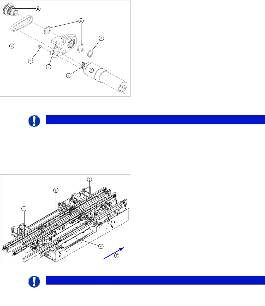
Parts
▪ [00359917-xx ] Synchroflex toothed belt 1315 long
for input conveyor
▪ [00356850-xx ] Synchroflex toothed belt 1500 long for
placement area
▪ [00364847-xx ] Synchroflex toothed belt 1160 long for
output conveyor
Legend
1. Input belt
2. Placement area
3. Output belt
4. Lifting table
NOTICE
The following diagrams apply to the standard conveyor system (fixed side - right). Depending
on the conveyor side (left or right), either the hexagon shaft guided block or the DC geared mo-
tor will be fitted.