00195376-05_SM_D1_D1i_D2_D2i_EN.pdf - 第115页
Service Work 4.4.2 Removal/Installation of Head Front Part C&P6/12 Head Service Manual SIPLACE D1/D1i/D2/D2i 115 4.4.2 4 . 4 . 2 R e m o v a l/ I n s t a lla t io n o f H e a d F r o n t P a r t Removal/Installation …
Service Work
C&P6/12 Head 4.4.1 Replacing the C&P6/12 Head (D1 D2)
114 Service Manual SIPLACE D1/D1i/D2/D2i
Removal
Installation
See also
6.5.1 Calibrating the C&P Head and Cameras [ ➙ 232]
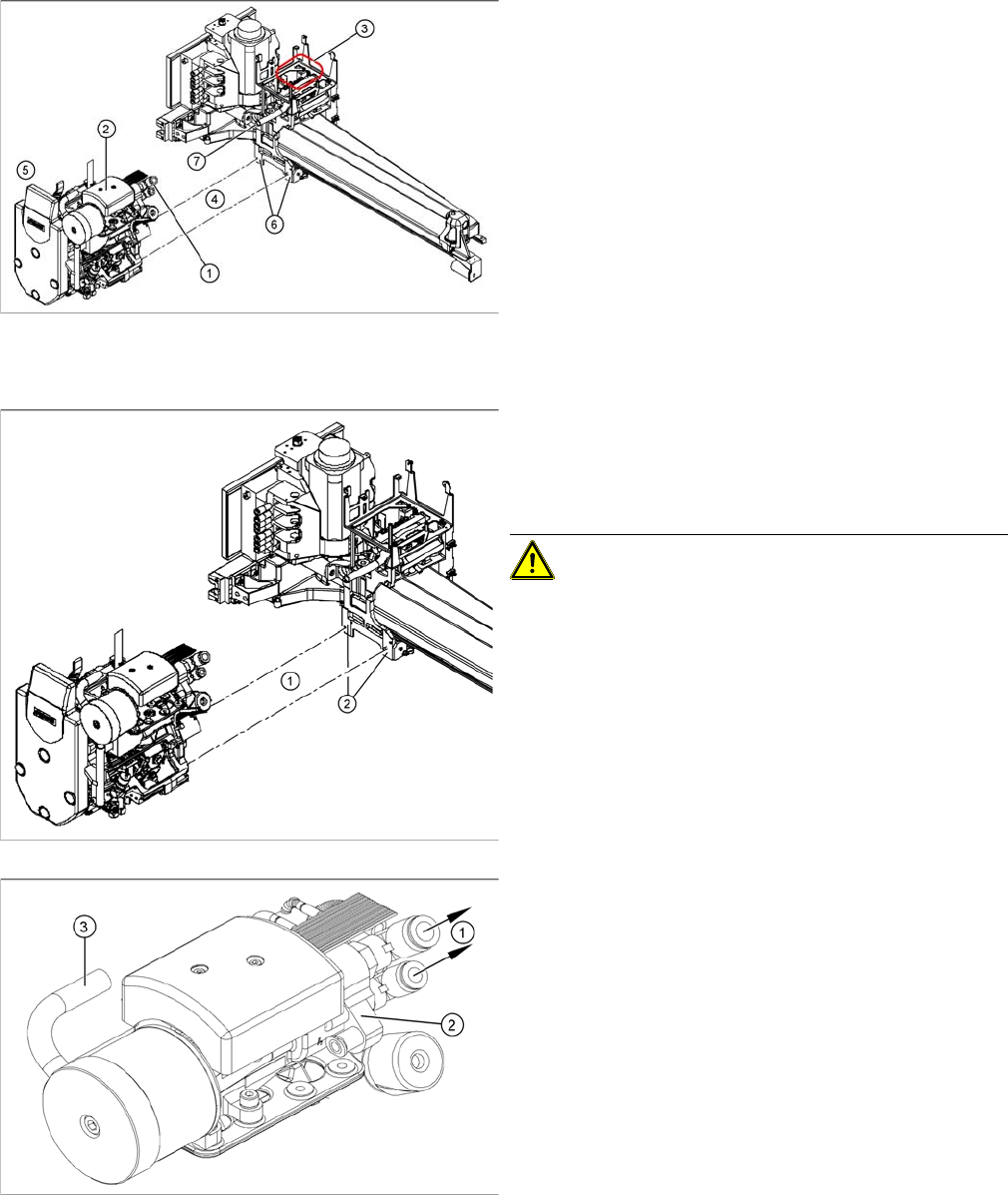
► Remove the compressed air hoses (1) from the pneu-
matic coupling of the vacuum generator (2).
► Loosen the press-fit connection to the C&P head
((5) from the gantry head distributor ((3) = installation
position).
► Loosen the 4 screws (4) fastening the C&P head.
► Unplug the hose to the vacuum distributor connection
disk.
► Carefully pull the C&P head away from the parallel
pins (5) on the head mount (6) and remove the head
from the machine.
► Make sure that all contact surfaces and pins are
clean.
► Carefully move the C&P head towards the head
mount (2).
CAUTION! Make sure that the cables and sili-
con hoses are not pinched.
► Make sure that the parallel pins on the head mount
slide into the holes drilled into the back part of the
C&P head.
► Carefully push the C&P head towards the head
mount until it lies flat against it.
► Fix the C&P head with the 4 screws provided (1).
► Reconnect the compressed air hoses (1) to the pneu-
matic coupling of the vacuum generator (2) and re-
store all hose connections (3).
► Reconnect to the electricity system.
► Use the SITEST program to calibrate the C&P head.
Service Work
4.4.2 Removal/Installation of Head Front Part C&P6/12 Head
Service Manual SIPLACE D1/D1i/D2/D2i 115
4.4.2
4.4.2 Removal/Installation of Head Front Part
Removal/Installation of Head Front Part
Parts, equipment and tools
▪ Set of Allen keys
▪ Torx Allen screwdriver TX8 [03080081-xx]
▪ Calibration tool version 3 [03010565-xx]
▪ Assembling instruction for "component sensor" [00193356-xx], if necessary
Removal
NOTICE
Avoid confusing the front and back sections of different heads.
The front and back parts of each specific head belong together.
► Make sure that the front and back part of the head always have the same serial number.
Do not confuse these parts with parts from other heads, which have different serial num-
bers.
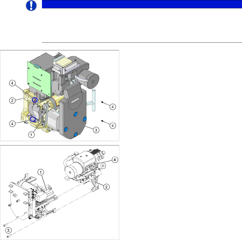
1. Front part
2. Back part
3. Intermediate distributor (under the cover)
4. 4x fastening screws for the front part of the head
1. Front part
2. Back part
3. Fastening screws for the front part of the head (total
of 4 screws)
4. Compressed air hose for air blast.
Service Work
C&P6/12 Head 4.4.2 Removal/Installation of Head Front Part
116 Service Manual SIPLACE D1/D1i/D2/D2i
► Switch off the machine and secure it to prevent unauthorized reactivation.
► X series/SX4/DX4: Unplug the connection cable from the sockets in the head adapter and Vision dig-
ital.
► DX1/DX2: Unplug the connection cable from the sockets in the base adapter and Vision digital..
► Remove the compressed air hose for the air blast.
► DLM3 only: If required, loosen the screws fastening the C&P12 component sensor option. Observe
the assembly instructions "component sensor" [00193356-xx].
► Loosen the four screws fastening the front part of the head.
► Pull the front part of the C&P head off the parallel pins on the back part and place it on a clean, soft
and ESD-proof surface.
► You will find the vacuum distributor block loose (unconnected) on the back part of the machine. Re-
move this vacuum distributor block.
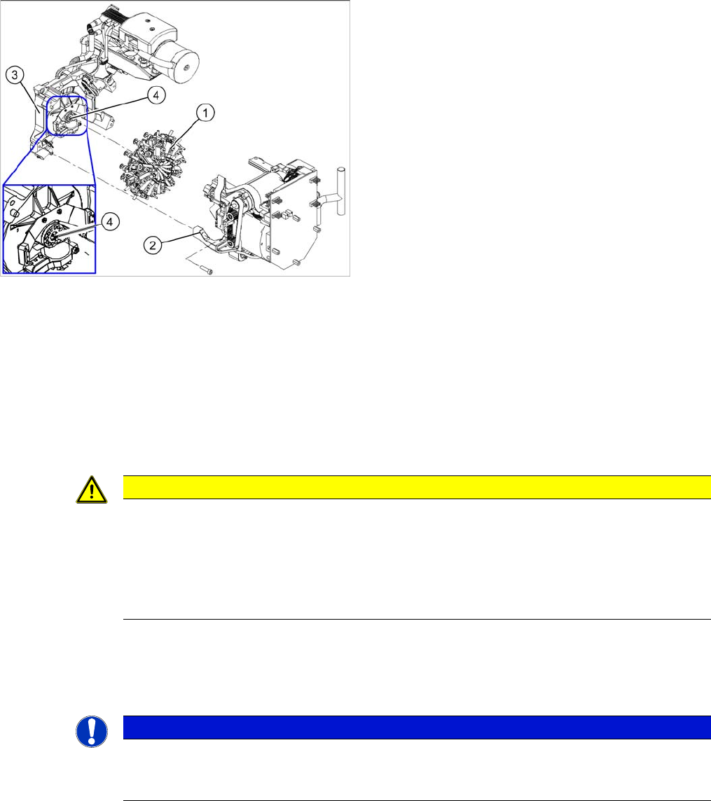
1. Star
2. Front part
3. Back part
4. Vacuum distributor block
CAUTION
Keep hold of the placement head and make sure the star position is correct!
► When you undo the last screw, hold the C&P head so that it does not accidentally drop off
the back part.
► When you remove the front part of the C&P head, make sure that the star is rotated roughly
30° or 15° out of the vertical sleeve position. If not, the valve plunger will remain attached
to the valve adjustment drive.
NOTICE
Vacuum distributor block
The vacuum distributor block is normally clamped between the front and back parts of the ma-
chine and transmits the vacuum for the holding circuit.