00195376-05_SM_D1_D1i_D2_D2i_EN.pdf - 第25页
Overview 3.2.3 Power Supply Unit Electrical System Service Manual SIPLACE D1/D1i/D2/D2i 25 3.2.3.2 3 . 2 . 3 . 2 P o s it io n o f P r o t e c t iv e C o n t a c t o r C o m b in a t io n a n d S e r v ic e S o c k e t P…
Overview
Electrical System 3.2.3 Power Supply Unit
24 Service Manual SIPLACE D1/D1i/D2/D2i
3.2.3
3.2.3 Power Supply Unit
Power Supply Unit
3.2.3.1
3.2.3.1 Supply Voltages
Supply Voltages
The power supply unit provides the following supply voltages:
▪ 200 V for the servo amplifier of the X and Y axes in the axis unit
▪ 150 V / 4 V- for the servo amplifier of the star in the axis unit
▪ 40 V for the servo amplifier of the Z and DP axes in the axis unit
▪ 52 V for the DC/DC converter in the subdistributor
▪ 40 V for the changeover tables and the PCB handling system
▪ 8 V for the changeover tables
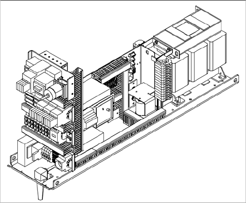
Power supply unit
The power supply unit is located in the left of the central
machine section. A lockable door prevents unauthorized
access to the unit.
Overview
3.2.3 Power Supply Unit Electrical System
Service Manual SIPLACE D1/D1i/D2/D2i 25
3.2.3.2
3.2.3.2 Position of Protective Contactor Combination and Service Socket
Position of Protective Contactor Combination and Service Socket
Service socket
The service socket is located in the power supply unit and is protected by the cover. It can only be used
if the placement system is connected to the main power supply via a 5-wire connection (L1, L2, L3, N,
and PE). If a 4-wire connection is used - without N - the socket can not be used.
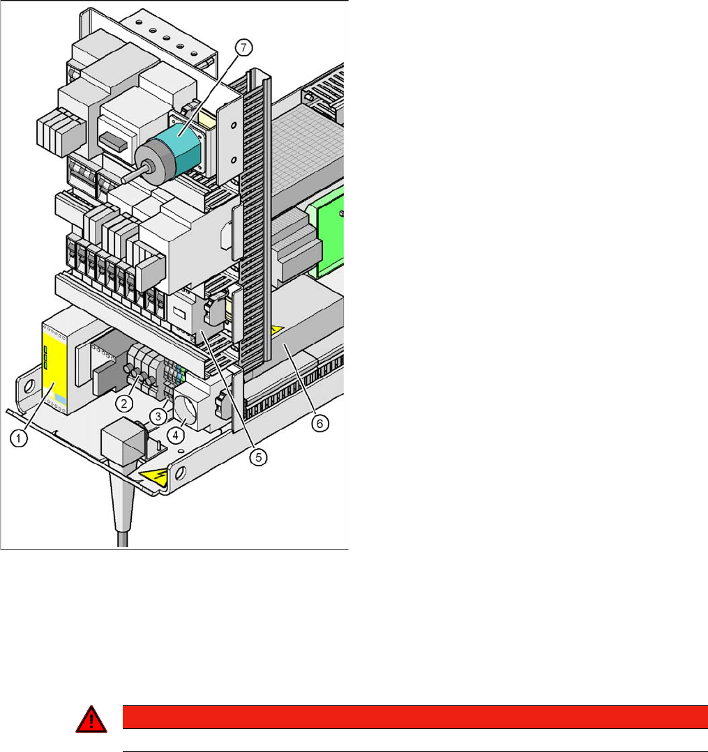
Position of protective contactor combination and service
socket
Legend
1. Protective contactor combination K1
2. Fuses FU, FV, FW, FBU
3. Infeed terminal X1
4. BU1 service socket
5. Z2 reactor
6. Main power filter Z1
7. S1 main power switch
Protective contactor combination 3TK2825
The protective contactor combination is located in the
power supply unit. It is used to monitor the EMERGENCY
STOP circuits and safety equipment.
There are three conditions that must be fulfilled in order
to activate the protective contactor combination:
▪ The "software enable" signal must have been sent.
▪ The EMERGENCY STOP loop must be closed.
▪ The start button must have been pressed.
The front side of the protective contactor combination has
three green LEDs for displaying the operational mode:
▪ The "Power" LED indicates that voltage is present.
▪ The "Channel 1" and "Channel 2" LEDs light up if the
start button has been pressed, the EMERGENCY
STOP loop is closed and the signaling circuit is not
signaling a fault status.
DANGER
Observe the safety instructions for lethal voltages, even when the machine is switched off.
Overview
Electrical System 3.2.3 Power Supply Unit
26 Service Manual SIPLACE D1/D1i/D2/D2i
3.2.3.3
3.2.3.3 EMERGENCY STOP Loop and Signaling Circuit
EMERGENCY STOP Loop and Signaling Circuit
Structure of the EMERGENCY STOP loop
The following contacts are connected in series and form the EMERGENCY STOP loop:
▪ Normally open (NO) contacts for the two protective cover switches
▪ Normally open (NO) contacts in the two protective switches for the cover flaps over the input and
output conveyors
▪ Normally open (NO) contacts for the two EMERGENCY STOP buttons
▪ Normally open (NO) contacts for the two component trolleys
▪ Normally open (NO) contacts for the two cover flaps (not available for D1, available as option for D2),
located above the pushbuttons and used to raise the changeover tables.
▪ Channels 1 and 2 of the protective contactor combination K1
Structure of the signaling circuit
The four signaling contacts (2x hoods, 2 x flaps) for the covers are connected in parallel and form the
"cover signal" circuit. If one or more hoods or flaps are opened, the contacts close, and the 24 V signal
is sent to the I/O module, signaling that one of the cover hoods is open.
The two signaling contacts for the EMERGENCY STOP buttons are connected in parallel and form the
"EMERGENCY STOP push-button signal circuit". When an EMERGENCY-STOP button is pressed, a
24 V signal is sent to the I/O module and signals that one of the EMERGENCY-STOP buttons has been
pressed.
The two signaling contacts for the pushbutton cover flaps (not available for D1, available as option for
D2), are connected in parallel. They form the "Flap signal" circuit. If one or more flaps are raised, a 24 V
signal is applied to the CAN bus and signals that one of the cover flaps is not closed.
The two signaling contacts for the component trolleys are connected in series and form the "Changeover
table" signal loop. If a component trolley is missing, a 0 V signal will be present at the I/O module. If all
trolleys are connected, the signal is approximately 16 V.
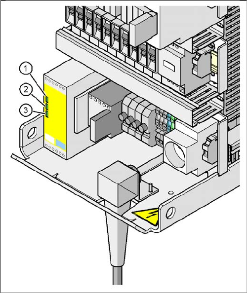
Signal LED on the protective contactor combination
Legend
1. Power
2. Channel 1
3. Channel 2
If the EMERGENCY STOP loop is closed, 24 VDC will be
present at channels 1 and 2 of the PCC. The two green
LEDs for channels 1 and 2 light up in addition to the green
Power ON LED.