00195376-05_SM_D1_D1i_D2_D2i_EN.pdf - 第71页
Service Work 4.2.5 Replacing the X Motor Unit 00333167-xx Gantries Service Manual SIPLACE D1/D1i/D2/D2i 71 4.2.5 4 . 2 . 5 R e p la c in g t h e X M o t o r U n it 0 0 3 3 3 1 6 7 - x x Replacing the X Moto r Unit 003331…
Service Work
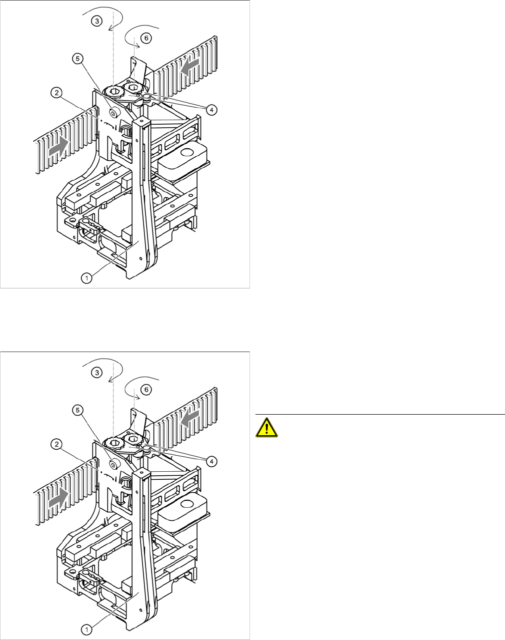
Gantries 4.2.4 Replacing the X-Axis Toothed Belt [03038308-xx]
70 Service Manual SIPLACE D1/D1i/D2/D2i
Installing the X-axis toothed belt
Settings
Fixing the X-axis toothed belt to the tension jack
Legend
1. Head mount
2. Tension jack
3. Synchronizing disk, long
4. Tensioning keys
5. Hexagon socket-head screw for tensioning the
toothed belt
6. Synchronizing disk, short
► Place the toothed belt around the synchronizing disk
of the X-axis motor unit.
► Thread the toothed belt in at the deflection unit.
► Thread both ends of the toothed belt in through the
openings on the tension jack (2), until it is run approx.
270° around the synchronizing disks (3).
► Fit the two tensioning keys (4). (See "4.2.2 Replacing
the Tensioning Keys [00329478-xx]" [ ➙ 62].)
Fixing the X-axis toothed belt to the tension jack
► Push the head mount (1) towards the X axis motor
unit, as far as the stop on the elastomeric spring.
► Turn the hexagon socket-head screw (5) to set the
belt tension to 44 Hz +/-1 Hz.
CAUTION! Do not overstretch the toothed belt
when adjusting the belt tension.
► Secure the hexagon socket-head screw (5) with the
locknut.
Service Work
4.2.5 Replacing the X Motor Unit 00333167-xx Gantries
Service Manual SIPLACE D1/D1i/D2/D2i 71
4.2.5
4.2.5 Replacing the X Motor Unit 00333167-xx
Replacing the X Motor Unit 00333167-xx
Tools and Equipment
▪ Set of DIN 911 Allen keys
▪ Cable ties
▪ Belt tension measuring device TSM [00326015-xx]
▪ "Measuring belt tensions" operating instructions
Parts
▪ X motor unit [00333167-xx]
▪ For SIPLACE D1 machines: Retrofitting guide for X axis heat sink [00195618-xx]
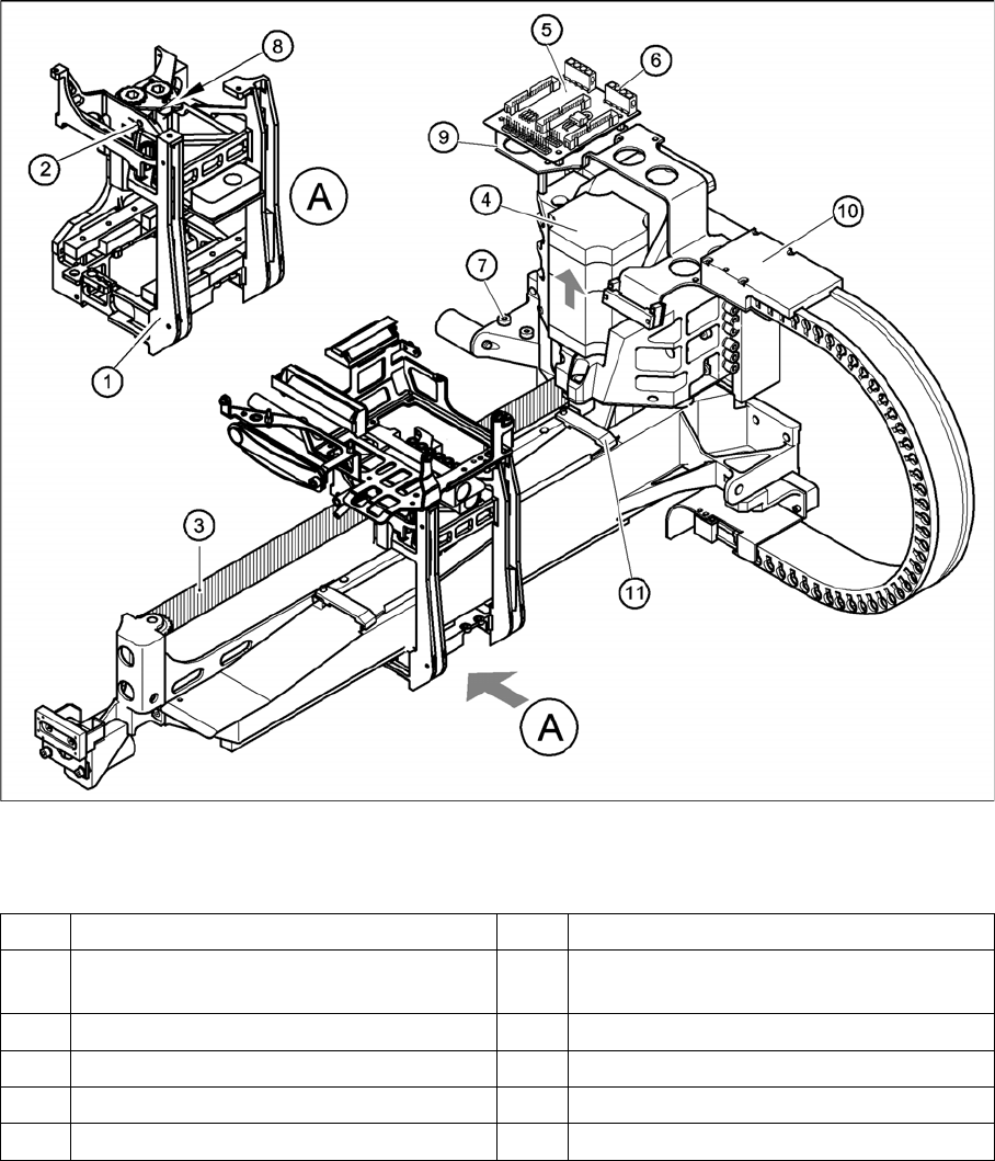
Removing the X-axis motor unit
Replacing the X motor unit (D4 shown as example)
Legend
1 Head mount 7 2 x M6 x 14 hexagon socket-head screws
2 M4 x 35 hexagon socket-head screw for
tensioning the X-axis toothed belt
8Locknut
3 Synchroflex X-axis toothed belt 9 Board holder
4 X-axis motor unit 10 Cable clamps
5 X/Y distributor 11 Cable clamp
6 X5 socket for X-axis motor

Service Work
Gantries 4.2.5 Replacing the X Motor Unit 00333167-xx
72 Service Manual SIPLACE D1/D1i/D2/D2i
► Switch off the machine and secure it to prevent unauthorized reactivation.
1 gantry D1 (2 gantries D2)
► Remove the cover strip on the crossbeam above the gantry concerned:
⇨ Unplug the fan cable. The fan is fixed to the cover strip.
⇨ Remove the cover strip (3 M6x8 hexagon socket-head screws).
► Cut the cable ties holding the X-axis motor cable.
► Remove the cable clamp for the flat ribbon cable (11).
► Disconnect all the plugs from the X/Y distributor (5).
► Remove the X/Y distributor (5).
► Remove the board holder for the X/Y distributor (9).
► Remove the cable holders (10) on the trailing cable.
► To relax the toothed belt (3), proceed as follows:
⇨ Loosen the locknut (8) and
⇨ Turn the hexagon socket-head screw (2) counterclockwise.
► Loosen the two M6 x 14 hexagon socket-head screws (7) fixing the X motor unit (4).
► Pull the X motor unit (4) up and out,
► at the same time pushing the board holder slightly to the side.
DANGER
POWERFUL MAGNETIC FIELD
► Always follow the special safety instructions when working in the vicinity of powerful mag-
netic fields.