00195376-05_SM_D1_D1i_D2_D2i_EN.pdf - 第21页
Overview 3.1.4 SIPLACE D4 Electrical System Service Manual SIPLACE D1/D1i/D2/D2i 21 3.2 3 . 2 E le c t r ic a l S y s t e m Electrical System Position of the modules Position of the mod ules Legend See also 3.3.2 Ov …
Overview
D-Series - General 3.1.3 SIPLACE D3
20 Service Manual SIPLACE D1/D1i/D2/D2i
3.1.3
3.1.3 SIPLACE D3
SIPLACE D3
3.1.4
3.1.4 SIPLACE D4
SIPLACE D4
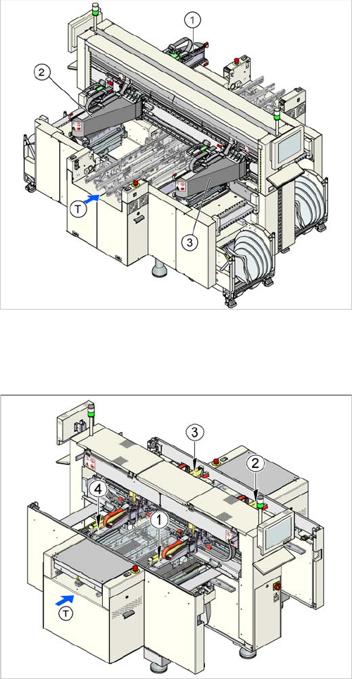
SIPLACE D3 with three gantries
Overview
▪ 3 gantries
▪ 3 placement heads
▪ Component spectrum 01005 – 85 x 85 mm / 125 x 10
mm max. 200 x 125 mm
▪ Placement performance: up to 30,100 components
per hour
▪ Placement accuracy: up to 22 µm at 3 sigma
▪Placement force: 1 N to 30 N
▪ 5-part conveyor with bumper function
▪ Locations:
For more details, refer to the D3 specifications.
SIPLACE D4 with four gantries
Overview
▪ 4 gantries
▪ 4 placement heads
▪ Component spectrum: 01005 – 18.7 x 18.7 mm
▪ Placement performance: up to 60,000 components
per hour
▪ Placement accuracy: up to 60 µm at 3 sigma
▪ Placement force: 2.4 N to 5 N
▪ 5-part conveyor with bumper function
▪ Locations:
For more details, refer to the D4 specifications.
Overview
3.1.4 SIPLACE D4 Electrical System
Service Manual SIPLACE D1/D1i/D2/D2i 21
3.2
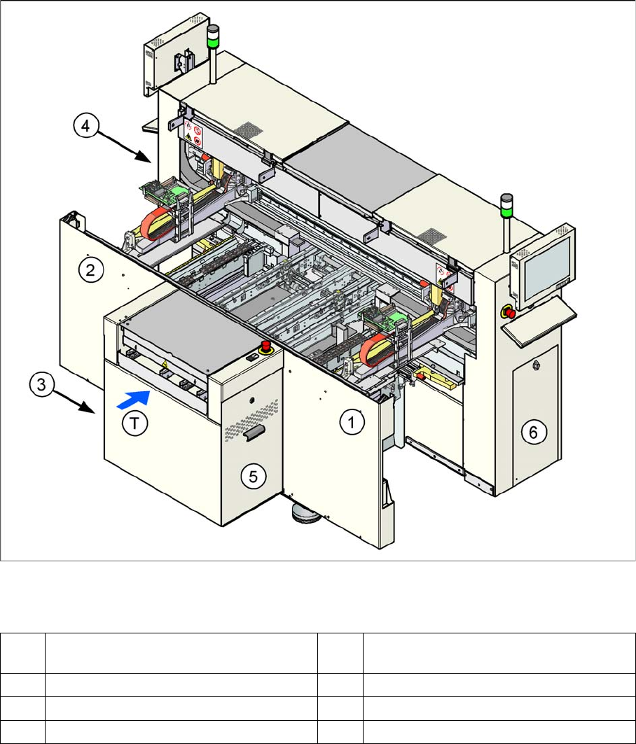
3.2 Electrical System
Electrical System
Position of the modules
Position of the modules
Legend
See also
3.3.2 Overview of Boards [ ➙ 33]
1 Subdistributor (TSP201, ...) (under the cov-
er)
4 Power supply unit
2 Main distributor (under the cover) 5 Axis unit
3 Computer unit 6 Pneumatic unit
T Transport direction
Overview
Electrical System 3.2.1 Axis Unit
22 Service Manual SIPLACE D1/D1i/D2/D2i
3.2.1
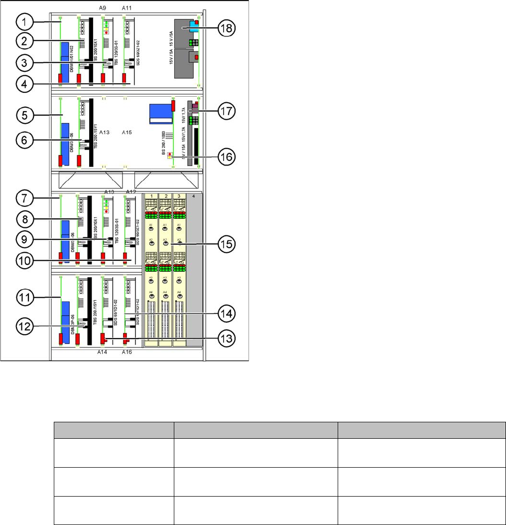
3.2.1 Axis Unit
Axis Unit
Overview of Settings
Axis unit (D2 as example)
Legend
1. X-axis brake board, gantry 1
2. X-axis servo card, gantry 1
3. Star axis servo card, gantry 1
4. Z-axis servo card, gantry 1
5. Y-axis brake board, gantry 1
6. Y-axis servo card, gantry 1
7. X-axis brake board, gantry 2 (for D2 only)
8. X-axis servo card, gantry 2 (for D2 only)
9. Star axis servo card, gantry 2 (for D2 only)
10. Z-axis servo card, gantry 2 (for D2 only)
11. Y-axis brake board, gantry 2 (for D2 only)
12. Y-axis servo card, gantry 2 (for D2 only)
13. DP axis servo card, gantry 1
14. DP axis servo card, gantry 2 (for D2 only)
15. 2 A364 axis cards (D2 has 3 A364 axis cards)
16. Ballast circuit
17. Power supply 5V/15A, 2x15V/5A
18. Power supply 15V/5A
Description Setting Values
Complete axis unit re-
placed
Set the DIP switch for the relevant
location
At placement area 1(OFF/OFF)
Axis card A 364 Install firmware for the relevant axis See "4.1.4 Replacing the A364 Axis
Card" [ ➙ 57].
Servo cards No settings required The servo card for the respective axis
is defined by the hardware.